56
MULTI F / MULTI F MAX Outdoor Unit Installation Manual
Due to our policy of continuous product innovation, some specifications may change without notification.
©LG Electronics U.S.A., Inc., Englewood Cliffs, NJ. All rights reserved. “LG” is a registered trademark of LG Corp.
MULTI
F
MAX
MULTI
F
Indoor Unit Terminal Block
A Unit
Indoor Unit Terminal Block
B Unit
Indoor Unit Terminal Block
C Unit
Indoor Unit Terminal Block
D Unit
Indoor Unit Terminal Block
E Unit
Indoor Unit Terminal Block
F Unit
Indoor Unit Terminal Block
G Unit
Indoor Unit Terminal Block
H Unit
Multi F LMU18CHV Multi F LMU24CHV
Multi F LMU30CHV and LMU36CHV
Multi F MAX LMU480HV and LMU540HV
BD Unit (A)
BD Unit (A )
A Room B Room C Room D Room A Room B Room C Room D Room
BD Unit (B )
BD Unit (B)
1(L1) 2(L2) 3(A) 1(L1) 2(L2) 3(B) L1 L2
L(L1) N(L2) S L(L1) N(L2) S
1(L1) 2(L2) 3
L(L1) N(L2) S
1(L1) 2(L2) 3
L(L1) N(L2) S
1(L1) 2(L2) 3
L(L1) N(L2) S
1(L1) 2(L2) 3
L(L1) N(L2) S
1(L1) 2(L2) 3
L(L1) N(L2) S
1(L1) 2(L2) 3
L(L1) N(L2) S
1(L1) 2(L2) 3
L(L1) N(L2) S
1(L1) 2(L2) 3
L(L1) N(L2) S
• The communications cable (con-
necting cable) from the outdoor
unit to the indoor unit should
be isolated from the electrical
ZLULQJRIH[WHUQDOGHYLFHVVXFKDV
computers, elevators, radio and
television broadcasting facilities,
and medical imaging offices. Com-
munication problems can arise
from electrical noise.
•
Do not install the power
wiring to the outdoor unit and the
power wiring / communications
cable (connecting cable) to the
indoor units in the same conduit.
These wiring / cables should have
separate conduits that are placed
a reasonable distance apart. Com-
munication problems can arise
from electrical noise.
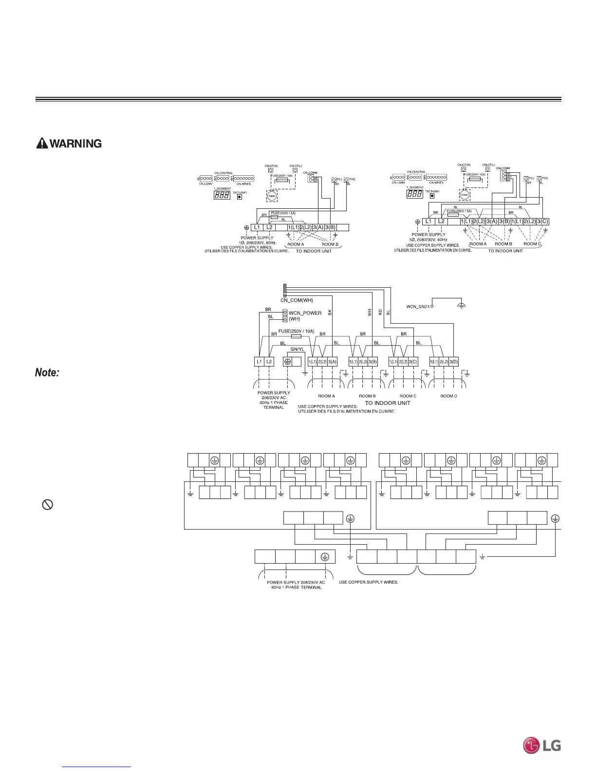
Figure 77: Detailed View of Outdoor Unit Terminal Blocks / Connections.
• Secure all field wiring connections
with appropriate wire strain relief.
Improperly securing wires will
create undue stress on equipment
power lugs. Inadequate connec-
tions may generate heat, cause a
fire and physical injury or death.
• Properly tighten all power lugs.
/RRVHZLULQJPD\RYHUKHDWDW
connection points, causing a fire,
physical injury or death.
• 5HSODFHDOOFRQWUROER[DQGSDQHO
covers. If cover panels are not
installed securely, dust, water and
animals may enter the outdoor
unit, causing fire, electric shock,
and physical injury or death.
&RQQHFWLQJWKH3RZHU:LULQJ&RPPXQLFDWLRQV&DEOHWR,QGRRU8QLWV
1. Connect power wiring / communications cable (connecting cable) from the outdoor unit to the individual indoor unit terminals following the
wiring diagrams on the outdoor unit and indoor unit control covers.
2. Ensure that the terminal board numbers (A, B, C; 1, 2, 3) and wiring color on the outdoor unit matches the terminal number and wiring col-
or on the indoor unit. (Terminal board numbers are arranged from top to bottom in order from 1 to 3.)
3. Provide strain relief by securing the wiring / cable to the indoor unit with the factory-supplied clamps.
4. For more installation information for specific indoor units, refer to the separate indoor unit installation manuals on www.lg-vrf.com.
Connecting the Power Wiring / Communications Cable to the Outdoor Unit, continued.
WIRING
Power Wiring and Communications Cable Connections
 Loading...

