57
Wiring
Due to our policy of continuous product innovation, some specifications may change without notification.
©LG Electronics U.S.A., Inc., Englewood Cliffs, NJ. All rights reserved. “LG” is a registered trademark of LG Corp.
MULTI
F
MAX
MULTI
F
General Instructions
• Always connect power wiring / communications cable matching
the BD unit terminals to their respective indoor units (Example for
three-port BD Unit PMBD3630: A, B, and C).
• Follow the instructions on the nameplates and connect wiring /
cables of the outdoor unit and indoor units to the correct terminals
(1, 2, 3). Always attach each ground wire separately to a ground-
ing screw.
• After completion, secure wiring with wire clamps. Secure wiring
firmly to the indoor unit.
'RQRWXVHWDSSHGZLUHVH[WHQVLRQFRUGVRUVWDUEXUVWW\SHFRQQHFWLRQVDVWKH\PD\FDXVHRYHUKHDWLQJ¿UHHOHFWULFVKRFNphysical injury or
death.
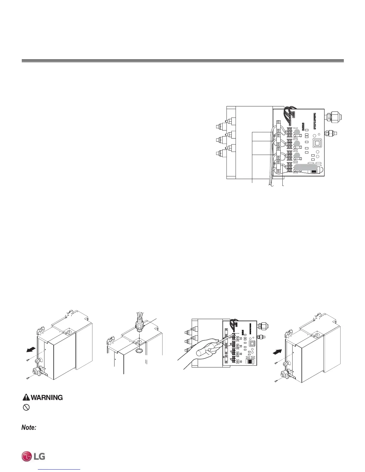
BD Unit Wiring Connection Procedure
1. Remove the BD unit control cover. Unscrew the two (2) screws, and slide the cover off the BD frame following the arrows in the diagram
(Step 1).
2. Draw the power wiring / communications cable through the field-supplied conduit so there is enough length to connect wiring / cable to the
terminals on the BD unit. Secure conduit to the BD unit using a field-supplied lock nut on the interior of the BD unit frame (Step 2).
3. Connect wiring / cable from the outdoor unit to the BD unit terminals, and from the BD unit terminals to the indoor unit terminals following
the wiring diagram on the outdoor unit control cover (Step 3). Allow 11-13/16 inches of slack in the wire harness. Attach wiring / cable to
the BD unit with clamps at four (4) locations.
4. Replace the BD unit control cover following the arrows in the diagram. Tighten the two (2) screws to finish (Step 4).
Lock nut (field supply)
Conduit (field supplied)
Lock nut (field supplied)
Step 1
Step 2
Step 3
Step 4
“A” Room
A
B
C
CN-PWR
Connection Wire to Indoor Units Connection Wire from Outdoor Unit
“B” Room
“C” Room
&RQQHFWLQJWKH3RZHU:LULQJ&RPPXQLFDWLRQV&DEOHWRWKH%UDQFK
Distributor (BD) Unit (Multi F MAX Systems Only)
Always refer to the circuit diagram on the inside of the outdoor unit control cover.
Figure 78: Interior View of a BD Unit (Three-Port PMBD3630 Example
Shown).
Figure 79: BD Unit Wiring Steps.
WIRING
Power Wiring and Communications Cable Connections
 Loading...

