40
MULTI F / MULTI F MAX Outdoor Unit Installation Manual
Due to our policy of continuous product innovation, some specifications may change without notification.
©LG Electronics U.S.A., Inc., Englewood Cliffs, NJ. All rights reserved. “LG” is a registered trademark of LG Corp.
MULTI
F
MAX
MULTI
F
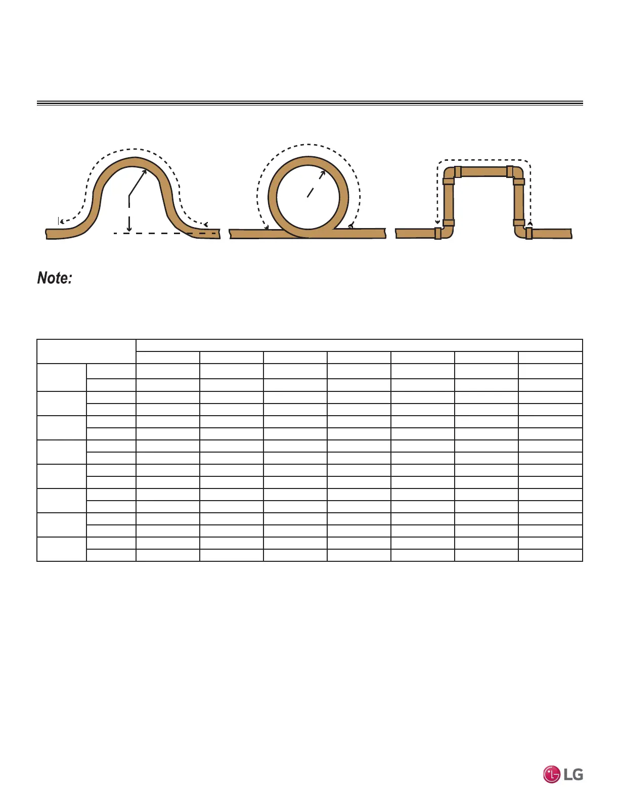
Figure 26: Coiled Expansion Loops and Offsets (Plan View).
Anticipated Linear
Expansion (LE) (in.)
Nominal Tube Size (OD) inches
1/4 3/8 1/2 3/4 1 1-1/4 1-1/2
1/2
R
1
6789111213
L
2
38 44 50 59 67 74 80
1
R
1
9 101113151718
L
2
54 63 70 83 94 104 113
1-1/2
R
1
11 12 14 16 18 20 22
L
2
66 77 86 101 115 127 138
2
R
1
12 14 16 19 21 23 25
L
2
77 89 99 117 133 147 160
2-1/2
R
1
14 16 18 21 24 26 29
L
2
86 99 111 131 149 165 179
3
R
1
15 17 19 23 26 29 31
L
2
94 109 122 143 163 180 196
3-1/2
R
1
16 19 21 25 28 31 34
L
2
102 117 131 155 176 195 212
4
R
1
17 20 22 26 30 33 36
L
2
109 126 140 166 188 208 226
1
R = Centerline Length of Pipe.
2
L = Centerline Minimum Radius (inches).
Table 18: Radii of Coiled Expansion Loops and Developed Lengths of Expansion Offsets.
R
L
L
R
L
Large Tubing U-bend (>3/4 in.) Loop
Small Tubing U-bend (<3/4 in.)
All expansion loops and offsets must be installed in the horizontal plane to prevent the possibility of trapping oil. Loops and offsets in vertical risers
must also be installed in a horizontal plane.
COPPER EXPANSION AND
CONTRACTION
 Loading...