Do you have a question about the LG Multi V and is the answer not in the manual?
Covers electrical work, grounding, and professional installation for safety.
Lists various indoor and outdoor unit model designations and their types.
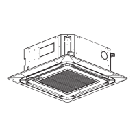
Details the physical design and forms of different indoor unit types.
Explains the coding system used for model names of indoor and outdoor units.
Introduces the ARU* series of outdoor units for detailed function explanation.
Outlines the operational functions of the ARU* series outdoor units.
Details technical specifications for HR units, including capacity, dimensions, and connections.
Explains the function of various components within the HR unit system.
Illustrates the refrigerant piping configurations for HR units.
Shows the electrical wiring connections for HR units.
Describes the operational functions and controls of the HR units.
Covers switch setup, addressing, and valve configuration for specific HR unit PCB models.
Details switch setup, addressing, and valve configuration for different HR unit PCB models.
Outlines pre-test run checks, abnormality handling, and setting verification for the system.
Lists common component failures, their causes, and troubleshooting methods.
Provides detailed procedures for checking critical components like compressors and motors.
Explains error codes and their corresponding causes and troubleshooting steps.
| Type | VRF (Variable Refrigerant Flow) |
|---|---|
| Compressor Type | Scroll |
| Refrigerant | R410A |
| Energy Efficiency | High |
| Control System | Centralized and individual control options |
| Indoor Units | Multiple types available (e.g., ceiling cassette, wall-mounted, ducted) |