Wiring Diagrams
- 47 -
Copyright © 2020 LG Electronics Inc.
All rights reserved. Only training and service purposes.
Wiring Diagrams
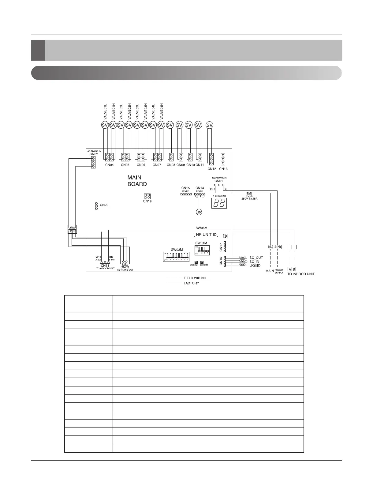
1. HR Units
CN04 Solenoid valve 01L/H(For room1)
CN05 Solenoid valve 02L/H(For room2)
CN06 Solenoid valve 03L/H(For room3)
CN07 Solenoid valve 04L/H(For room4)
CN08 Solenoid valve 01 (Bypass for room1)
CN09 Solenoid valve 02 (Bypass for room2)
CN10 Solenoid valve 03 (Bypass for room3)
CN11 Solenoid valve 04 (Bypass for room4)
CN12 Solenoid valve bypass
CN14 Sub cooling EEV
CN16(SC Out) Sensor, sub cooling out
CN16(SC In) Sensor, sub cooling in
CN18(Liquid) Sensor, liquid receiver
SW01M Solonoid valve number Setting(When manual address)
SW02M(1) Selecting, auto address() or manual address()
SW02M(2~3) Setting, total number of indoor connected
SW03M Setting, the address of indoor_10(When manual address)
SW04M Setting, the address of indoor_1(When manual address)
SW05M Setting, HR unit number