54
MULTI F / MULTI F MAX Outdoor Unit Installation Manual
Due to our policy of continuous product innovation, some specifications may change without notification.
©LG Electronics U.S.A., Inc., Englewood Cliffs, NJ. All rights reserved. “LG” is a registered trademark of LG Corp.
MULTI
F
MAX
MULTI
F
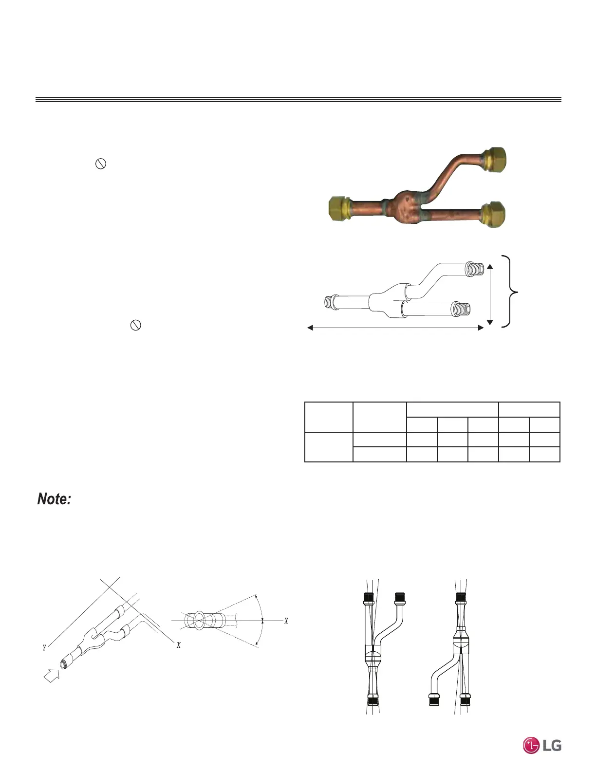
The LG-supplied Y-Branch kit PMBL5620 MUST be used when
installing two (2) branch distribution units in parallel on one (1) Multi
F MAX system.
Field-supplied fittings are not permitted. Each
Y-Branch kit includes two (2) Y-branches (one for the liquid line and
one for the vapor line) and insulation covers.
Y-branches can be installed in horizontal or vertical configurations.
When installed vertically, position the Y-branch so the straight
WKURXJKOHJLVRISOXPE:KHQLQVWDOOHGKRUL]RQWDOO\SRVLWLRQWKH
Y-branch so the take-off leg is level and shares the same horizontal
SODQHDVWKHVWUDLJKWWKURXJKOHJURWDWLRQ
Y-branches must be properly installed following instructions in the
applicable LG manual. Y-branches must always be installed with the
single port facing the outdoor unit and the two-port end facing the
branch distribution units.
Do not install Y-branches backwards
as refrigerant flow cannot make U-turns. The Y-branch kit must be
located at least three (3) feet from the outdoor unit. Provide a min-
imum of 20 inches between a Y-branch and the branch distribution
unit.
When a Y-branch is located in a pipe chase or other concealed
space, access doors must be provided for inspection access.
7KHHTXLYDOHQWSLSHOHQJWKRIHDFK<EUDQFKƍPXVWEHDGGHGWR
the main pipe segment entered into LATS piping design software.
Figure 54: <%UDQFK3RUW,GHQWL¿HU'LDJUDP
Figure 55: Y-Branch Dimensions Diagram.
Figure 56: +RUL]RQWDO&RQ¿JXUDWLRQ(QG9LHZ
Figure 57: <EUDQFK,QVWDOODWLRQ$OLJQPHQW6SHFL¿FDWLRQ
Viewed from A in direction of arrow
Horizontal
plane
Within 5°
A
Within 5°
Vertical Up
Configuration
Within ± 3°Within ± 3°
Vertical Down
Configuration
A
B
X
Y
1
2
3
A = To Outdoor Unit B = To Branch Distribution Unit
1
2
3
Multi F MAX Y-Branch Kit PMBL5620
• Design pressure is 551 psig.
• All dimensions in inches. Tolerance ±1/4 inch.
• Images are not to scale.
Table 30: Y-Branch Connection Diameters.
INSTALLING MULTI F MAX SYSTEMS
Model
Y-Branch
Type
3RUW,GHQWLÀHULQFK Dimensions
123XY
PMBL5620
Liquid 3/8 3/8 3/8 13.80 3.24
Vapor 3/4 3/4 3/4 12.48 3.02

 Loading...