9
ENGLISH
Limitati
ons on
the
height
of the
wall
(Refer
to 4
side
walls)
h2
h1
1500 (59)
Inlet
side
A
B
50500
(19-11/16’’)(19-11/16’’)
500
(19-11/16’’)
Front
side
500
(19-11/16’’)
240
(9-1/2’’)
or more
50 (2) or more
45° or
more
• The height of the wall on the front side must
be 1500 mm (59 inch) or less.
• The height of the wall on the inlet side must
be 500 mm (19-11/16 inch) or less.
• There is no limit to the wall on the side.
• If the height of the walls on the front and the
side are higher than the limit, there must be
additional space on the front and the side.
- Additional Space on the front side by 1/2 of h1
- Additional Space on the inlet side by 1/2 of h2
- h1 = A(Actual height) - 1500 mm (59 inch)
- h2 = B(Actual height) - 500 mm (19-11/16 inch)
Seasonal wind and cautions in winter
• Sufficient measures are required in a snow areas or severe cold
areas in winter so that product can be operated well.
• Get ready for seasonal wind or snow in winter even in other areas.
• Install a suction and discharge duct not to let in snow or rain.
• Install the outdoor unit In such a way that it should not come in
contact with snow directly. If snow piles up and freezes on the air
suction hole, the system may malfunction. If it is installed at snowy
area, attach the hood to the system.
• Install the outdoor unit at the higher installation console by 50 cm
(19.7 inch) than the average snowfall (annual average snowfall) if it is
installed at the area with much snowfall.
• Where snow accumulated on the upper part of the Outdoor Unit by
more than 10 cm (3.9 inch), always remove snow for operation.
- The height of H frame must be more than 2 times the snowfall
and its width shall not exceed the width of the product. (If width
of the frame is wider than that of the product, snow may
accumulate)
- Don't install the suction hole and discharge hole of the Outdoor
Unit facing the seasonal wind.
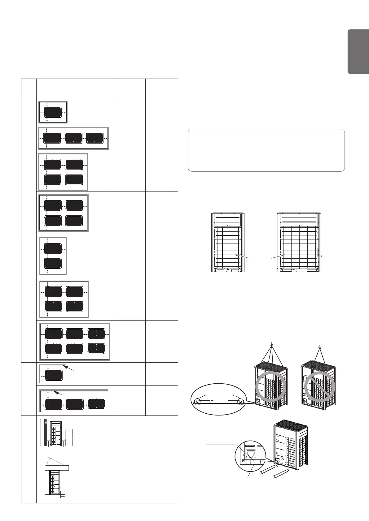
• When carrying the suspended, unit pass the ropes under the unit and
use the two suspension points each at the front and rear.
• Always lift the unit with ropes attached at four points so that impact
is not applied to the unit.
• Attach the ropes to the unit at an angle of 40 ° or less.
Locking points for
transportation ropes
Forklift Carrying Guide
Forklift Carrying Hole
LIFTING METHOD
INSTALLATION SPACE
Individual Installation
During the installation of the unit, consider service, inlet, and outlet
acquire the minimum space as shown in the figures below.
Category
Installation Space
Case 1
(10(13/32)≤Side
Space≤49(13/14))
Case 2
(Side Space
≥49(13/14))
4 sides
are
walls
A≥10 (13/32)
B≥300 (11-13/16)
C≥10 (13/32)
D≥500 (19-11/16)
A≥50 (1-31/32)
B≥100 (3-15/16)
C≥50 (1-31/32)
D≥500(19-11/16)
A≥10 (13/32)
B≥300 (11-13/16)
C≥10 (13/32)
D≥500 (19-11/16)
E≥20 (25/32)
A≥50 (1-31/32)
B≥100 (3-15/16)
C≥50 (1-31/32)
D≥500 (19-11/16)
E≥100 (3-15/16)
A≥10 (13/32)
B≥300 (11-13/16)
C≥10 (13/32)
D≥500 (19-11/16)
E≥20 (25/32)
F≥600 (23-5/8)
A≥50 (1-31/32)
B≥100 (3-15/16)
C≥50 (1-31/32)
D≥500 (19-11/16)
E≥100 (3-15/16)
F≥500 (19-11/16)
A≥10 (13/32)
B≥300 (11-13/16)
C≥10 (13/32)
D≥300 (11-13/16)
E≥20 (25/32)
F≥500 (19-11/16)
A≥50 (1-31/32)
B≥100 (3-15/16)
C≥50 (1-31/32)
D≥100 (3-15/16)
E≥100 (3-15/16)
F≥500 (19-11/16)
Rear
to
Rear
A≥10 (13/32)
B≥500 (19-11/16)
C≥10 (13/32)
D≥500 (19-11/16)
F≥900 (35-7/16)
A≥50 (1-31/32)
B≥500 (19-11/16)
C≥50 (1-31/32)
D≥500 (19-11/16)
F≥600 (23-5/8)
A≥10 (13/32)
B≥500 (19-11/16)
C≥10 (13/32)
D≥500 (19-11/16)
E≥20 (25/32)
F≥1200 (47-1/4)
A≥50 (1-31/32)
B≥500 (19-11/16)
C≥50 (1-31/32)
D≥500 (19-11/16)
E≥100 (3-15/16)
F≥900 (35-7/16)
A≥10 (13/32)
B≥500 (19-11/16)
C≥10 (13/32)
D≥500 (19-11/16)
E≥20 (25/32)
F≥1800 (70-7/8)
A≥50 (1-31/32)
B≥500 (19-11/16)
C≥50 (1-31/32)
D≥500 (19-11/16)
E≥100 (3-15/16)
F≥1200 (47-1/4)
Only 2
sides
are
walls
A≥10 (13/32)
B≥300 (11-13/16)
A≥200 (7-7/8)
B≥300 (11-13/16)
E≥400 (15-3/4)
Front
Front
Front Front
Front Front
Front
Front
Front
Front Front
Front Front
Front Front Front
Front
Front
Front
Front Front
No limit for the
height of wall
No limit for the height of wall
Front
[Unit : mm (inch)]
Remove the Rear Grille
• Remove the rear grille in snowy area.
• Make sure that heat exchanger should not be damaged.
Rear Grille
UXA UXB
1,MFL67221448,영영 2018. 10. 2. 영영 4:15 Page 9
 Loading...