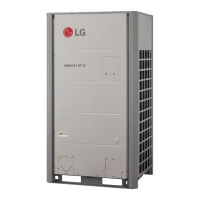
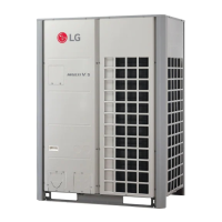
Do you have a question about the LG Multi V 5 ARUV144DTE5 and is the answer not in the manual?
Covers warnings, cautions, and general safety guidelines for appliance use.
Details required clearances for unit installation and airflow based on configuration.
Specifies anchor bolt placement for secure unit installation.
Details requirements for secure unit mounting and vibration reduction.
Explains correct flaring work for pipe connections to prevent gas leaks.
Crucial safety and operational steps for connecting refrigerant pipes and operating valves.
Instructions for connecting multiple outdoor units in series or parallel configurations.
Steps for preparing outdoor unit panels and using knock-outs for pipe and cable routing.
Details piping configurations for single outdoor unit systems (Y branch, Header).
Outlines piping methods for multi-unit systems, including Y branch and Header.
Illustrates methods for routing pipes from the front and bottom of the unit.
Explains header configurations and installation guidelines for multiple units.
Provides pipe diameter selection based on capacity, length, and conditions.
Specifies pipe diameters for indoor unit connections based on capacity.
Offers guidance on series connections between outdoor units, including oil trap usage.
Details fitting procedures for Y branch and Header configurations, including insulation.
Illustrates piping layouts for horizontal distribution of refrigerant.
Shows piping arrangements for vertical distribution of refrigerant.
Depicts piping configurations for mixed or complex distribution layouts.
Explains how to set up the vacuum mode for system evacuation.
Details the procedure to turn off the vacuum mode.
Describes the procedure for performing a nitrogen gas leak test on the system.
Explains the process of vacuum drying to remove moisture from the system.
Lists tools needed for refrigerant charging.
Provides formula and examples for calculating additional refrigerant charge.
Explains proper insulation techniques for refrigerant pipes to prevent condensation.
Details the types of cables for communication and their connections.
Guidelines for safely routing power and communication cables to prevent interference.
Explains accessing the control box and connecting communication and power cables.
Specifies types and dimensions for central control communication cables.
Details ground wire thickness requirements based on unit capacity.
Illustrates communication cable connections for single outdoor units.
Shows wiring diagrams for 2-unit systems with series or individual power supply.
Illustrates communication cable connections for 460V systems.
Provides wiring diagrams for 3-unit systems with series or individual power supply.
Shows communication cable connection methods (BUS vs. STAR type).
Details power and communication cable connections for UXB models.
Details power and communication cable connections for UXA models.
Explains how to check outdoor unit settings using DIP switches and the 7-segment display.
Describes the initial display sequence on the 7-segment LED after power-on.
Details DIP switch settings for Master and Slave units for configuration.
Step-by-step guide for performing automatic addressing of indoor units.
Instructions for setting optional functions using DIP switches and buttons.
Explains how to enable high static pressure compensation for airflow.
Lists maximum fan RPM settings for different operating steps.
Describes how to activate the night low noise function for reduced fan operation.
Explains how to set the ODU address using DIP switches.
Details how to adjust target pressure using the mode setting method.
Explains how to set the Low Ambient Kit using DIP switches.
Describes how to set the High Efficiency Mode for cooling operations.
Explains how to set the Auto Dust Removal Mode.
Details how to set the maximum compressor frequency limit.
Explains how to set the maximum ODU fan RPM limit.
Explains how to set Smart Load Control for efficiency.
Details how to set the humidity reference control mode.
Explains how to set up central control connection for indoor units.
Details how to set the compressor input current limit.
Explains how to set up the power consumption display feature.
Describes how to set the comfort cooling operation for energy saving.
Explains how error codes are displayed on units and remote controllers.
Details the meaning of 7-segment LED displays and error codes.
Defines the limit for refrigerant gas concentration in a room.
Steps to check and manage refrigerant concentration limits.
How to calculate room volume for determining refrigerant concentration.
Guidance on selecting an outdoor unit location to avoid sea wind exposure.
Information on the product's sound pressure emission levels.
| Brand | LG |
|---|---|
| Model | Multi V 5 ARUV144DTE5 |
| Category | Air Conditioner |
| Language | English |


 Loading...