50
ENGLISH
Self-Diagnosis Function
Error Indicator
- This function indicates types of failure in self-diagnosis and occurrence of failure for air condition.
- Error mark is displayed on display window of indoor units and wired remote controller, and 7 segment LED of outdoor unit control board as
shown in the table.
- If more than two troubles occur simultaneously, lower number of error code is first displayed.
- After error occurrence, if error is released, error LED is also released simultaneously.
Error Display
1st, 2nd, 3rd LED of 7 segment indicates error number, 4th LED indicates unit number.(* = 1: Master, 2: Slave 1, 3: Slave 2, 4: Slave 3)
Ex) 1051 : Error occurrence with error number 105 at No. 1 outdoor unit (=Master unit)
In case of indoor unit error occurrence, the error number is only shown at remote controller
without 7 segment LED of outdoor unit.
Ex) CH → 01 : Error occurrence with error number 01 (at remote controller)
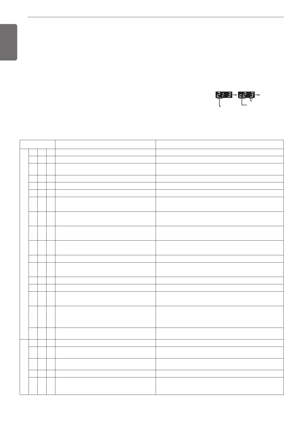
In case of compressor error occurrence, 7 segment LED of outdoor unit control board
will display its error number alternately with compressor number.
Ex) 213 → C23 : It means that compressor error occurred with Error No. 21 at No. 3 Outdoor unit (=Slave2)
* Refer to the DX-Venitilation manual for DX-Venitilation error code.
• 1 : Master outdoor unit error, 2 : salve 1 outdoor unit error
• 3 : slave2 outdoor unit error, 4 : slave3 outdoor unit error
Error No. of Compressor
Error No.
Error No. of Unit
Display Title Cause of Error
Indoor unit related error
0 1 - Air temperature sensor of indoor unit Air temperature sensor of indoor unit is open or short
0 2 - Inlet pipe temperature sensor of indoor unit Inlet pipe temperature sensor of indoor unit is open or short
0 3 -
Communication error : wired remote controller ÷
indoor unit
Failing to receive wired remote controller signal in indoor unit PCB
0 4 - Drain pump Malfunction of drain pump
0 5 -
Communication error : outdoor unit ÷ indoor unit
Failing to receive outdoor unit signal in indoor unit PCB
0 6 - Outlet pipe temperature sensor of indoor unit Outlet pipe temperature sensor of indoor unit is open or short
08 -
Hydro Kit Hot water storage tank Temperature
sensor
Pipe temperature sensor is open or short
0 9 - Indoor EEPROM Error
In case when the serial number marked on EEPROM of
Indoor unit is 0 or FFFFFF
1 0 - Poor fan motor operation
Disconnecting the fan motor connector / Failure of indoor
fan motor lock
1 1 -
Communication error : Hydro Kit Indoor unit ÷
Inv.PCB
Failing to receive Inv. PCB signal in indoor unit
1 2 - Hydro Kit Inv.PCB error Hydro Kit Inv.PCB error
13 -
Hydro Kit Solar heat piping temperature sensor
error
Pipe temperature sensor is open or short
1 4 - Hydro Kit Indoor unit Flow switch error Flow switch flow detection error
1 5 - Hydro Kit Liquid pipe Strange overheat Error Temperature sensor defective or hot water inflow
16 -
Hydro KitIndoor unit Inlet and Outlet pipe
Temperature sensor Error
Pipe temperature sensor is open or short
17 -
Hydro Kit Indoor unit Inlet pipe Temperature
sensor Error
Outside air Introduction duct Inlet pipe
Temperature sensor Error
Pipe temperature sensor is open or short
18 -
Hydro Kit Indoor unit Outlet pipe Temperature
sensor Error
Pipe temperature sensor is open or short
Outdoor unit related error
2 1 *
Outdoor Unit Inverter Compressor IPM Fault
Outdoor Unit Inverter Compressor Drive IPM Fault
2 2 *
Inverter PCB Input Over Current(RMS) of Master
Outdoor Unit
Outdoor Unit Inverter PCB Input Current excess (RMS)
2 3 *
Outdoor Unit Inverter Compressor DC Link Low or
High Voltage
System is turned off by Master Outdoor Unit DC Link Low/High
Voltage.
2 4 * Outdoor Unit High Pressure Switch
System is turned off by Master Outdoor Unit high pressure switch.
2 5 *
Outdoor Unit Input Voltage High/ Low Voltage
Over 537V or below 247V (ARUM***LTE5)
Over 310V or below 143V (ARUM***BTE5)
Over 598V or below 320V (ARUM***DTE5)
 Loading...