43
Installation Manual
Due to our policy of continuous product innovation, some specifications may change without notification.
©LG Electronics U.S.A., Inc., Englewood Cliffs, NJ. All rights reserved. “LG” is a registered trademark of LG Corp.
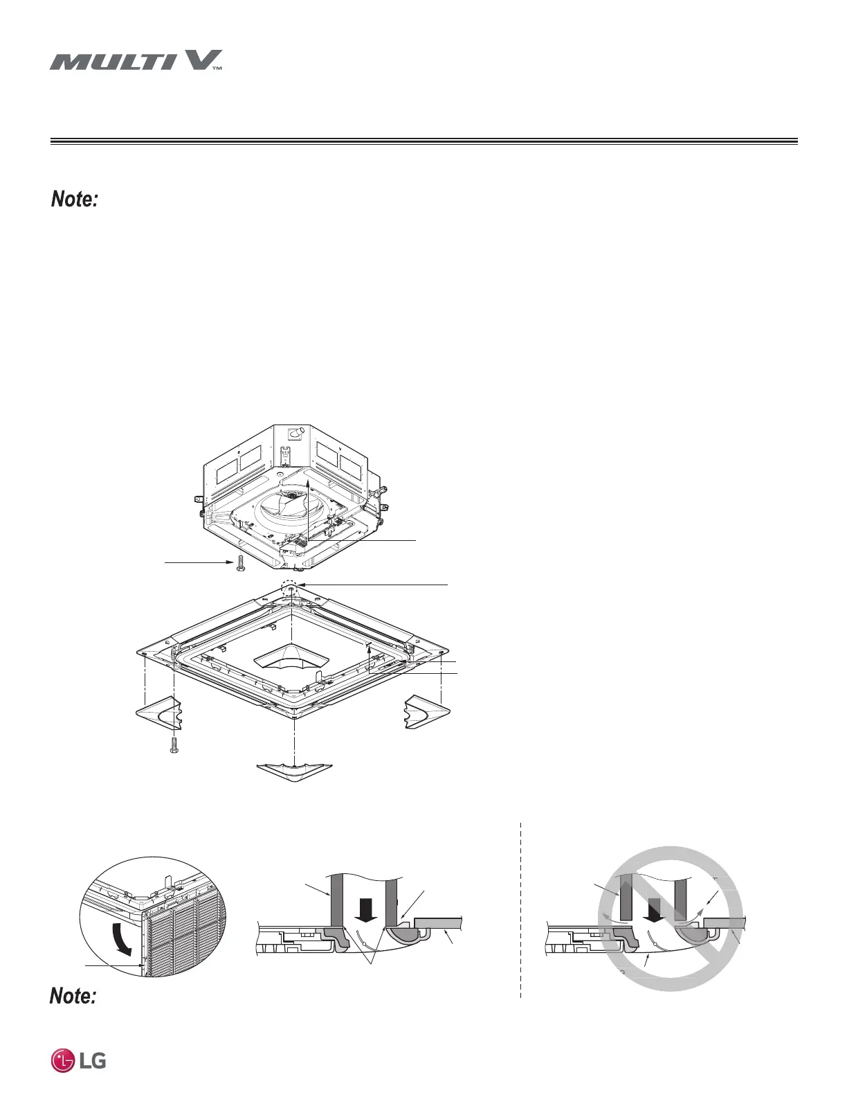
INSTALL DECORATION COVER
Inlet
Grill
Cassette
Frame
Ceiling Board
Decorative Panel
Air
Cool Air Leaking
Through Gap
Decorative Panel against Cassette
Frame with No Gap
Air
Cassette
Frame
No Air Gap
Ceiling Board
Correct Installation Incorrect Installation
Figure 37: Four-Way Cassette Decorative Cover Installation.
Figure 38: Swing Inlet Grille
Downward on the Four-Way Cas-
sette Indoor Unit Frame.
Decorative Cover
Louver Motor
Display
Lead Wire for
Louver Motor and
Display
Decorative Cover
Installation Screws
(Hexagon M5)
Cassette Frame
Control Box Cover
Piping Side
Decorative Cover Installation
Screws (M5 Hexagon; Tighten
Temporarily at Two [2] Places
about 3/8 in.)
,QVWDOOWKHGHFRUDWLYHFRYHUVQXJO\DQGZLWKRXWJDSV$Q\JDSVEHWZHHQWKHFHLOLQJDQGWKHFDVVHWWHIUDPHZLOOUHOHDVHFRRODLUZKLFKZLOOFDXVH
VZHDWLQJ:DWHUGURSVWKDWIDOOZLOOGDPDJHWKHVXUURXQGLQJFHLOLQJÀRRUDQGZDOOV
Figure 39: Properly Installing Decorative Cover Against the Four-Way Cassette Indoor Unit Frame.
Four-Way Decorative Cover Installation
• 'HFRUDWLYHFRYHULVDQRSWLRQDODFFHVVRU\WKDWLVVROGVHSDUDWHO\
• %HIRUHLQVWDOOLQJWKHGHFRUDWLYHSDQHODOZD\VUHPRYHWKHSDSHUWHPSODWHILUVW
1. Install the two decorative cover attaching screws (M5) on the cassette frame (factory supplied). Tighten only about 3/8 inch.
2. Remove the air inlet grille from the decorative cover. (Remove the hook for the air inlet grille cord.)
3. Hook the decorative cover key hole on the installed screws, and slide the panel so that the screws lock into the key hole edge.
4. Tighten completely the two initially installed screws, and install the two additional screws.
5. Connect the louver motor connector and display connector.
6. After tightening these screws, install the air inlet grille (including the air filter).
 Loading...