34 Outdoor Unit
Electrical Wiring
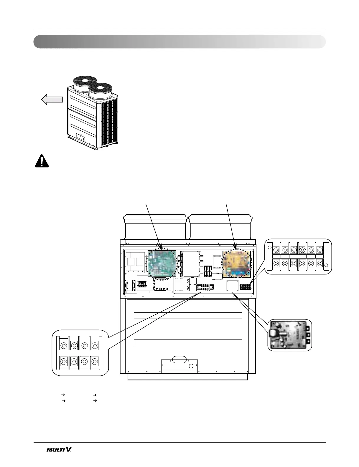
Control box and connecting position of wiring
- Remove all of the screws at front -upper panel, and remove the front panel by pulling it forward
- Connect indoor and outdoor units through the terminal block for
transmission lines. Outdoor units and connections to central
control systems go through the sub PCB for central control.
- When making an indoor/outdoor connection with shielded wiring,
connect the shield ground to the earth screw. When making a central
control system connection with shielded wiring, use the terminal block
for central control.
- For the distance from main power lines to transmission lines refer to
pages 35~37.
- Refer to pages 38~40 for automatic addressing and 45~49 for test run.
WARNING
The temperature sensor for outdoor air should not be exposed to direct sunlight.
-Take a appropriate cover to intercept direct sunlight.
C D Vcc GND A B
Inverter board Control board
Terminal block for indoor unit
transmission lines
-- Be careful for misconnection
or cross connection of the
transmission lines
- Be careful for the polarity of main
power lines
R(CB) R(TB), S(CB)
S(TB)
T(CB) T(TB), N(CB) N(TB)
(TB: terminal block, CB: circuit breaker)
Sub PCB for
simple central control
or internet control
 Loading...


