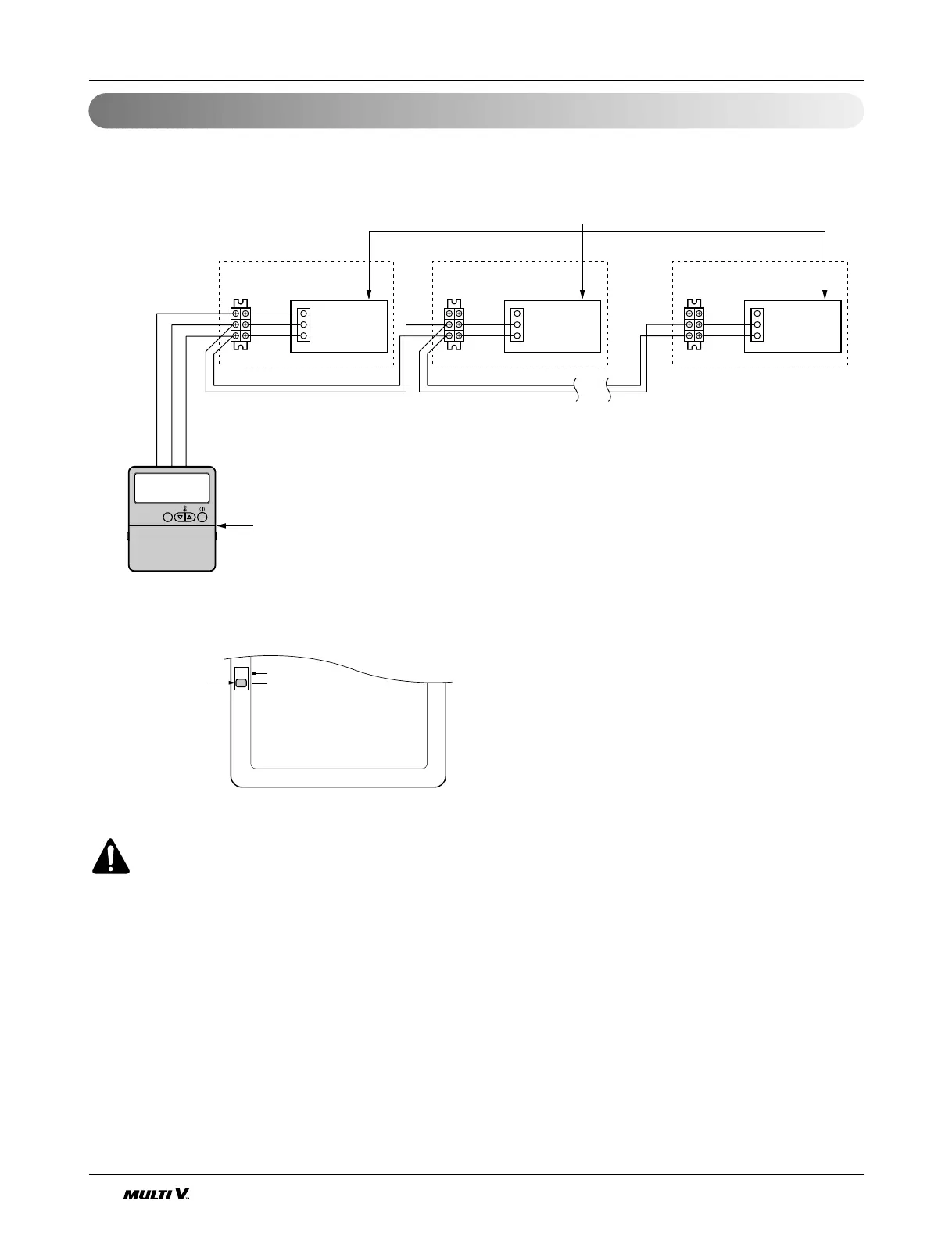
EasyManuals Logo

LG Multi V CRUN Series Installation Manual

LG Multi V CRUN Series
62 pages
To Next Page IconTo Next Page
To Previous Page IconTo Previous Page
Page #44 background imageLoading...
Page #44 background image
Group Control with Wired Remote Controller
44 Outdoor Unit
Electrical Wiring
Operation unit
ZONE
1234
Humidify
JET
AUTO
AUTO SWING OPERATION
FAN SPEED
Program set
SUB FUNCTION
SET TEMP
Room Temp
HI
MED
LO
Heater
Defrost
Filter
Preheat
Out door
Time
Timer
On
Set no. Time
Off
01 03 05 07 09 11 13 15 17 19 21 23
Indoor Unit 1
Terminal(Local Supply)
Block
Terminal(Local Supply)
Block
Terminal(Local Supply)
Block
Main PCB
#1
Main PCB
#2
Main PCB
#16
Wired Remote Controller
(Standard)
Indoor Unit 2
Main PCB
Indoor Unit 16
Connector
RED(12V)
YL(SIGNAL)
BR(GND)
RED(12V)
YL(SIGNAL)
BR(GND)
YL(SIGNAL)
BR(GND)
Connecting Cable(Local Supply)
Connector Connector
....
....
YL(SIGNAL)
BR(GND)
YL(SIGNAL)
BR(GND)
YL(SIGNAL)
BR(GND)
Remote
Controller
PCB
Single
Group
Slide Switch2
Using the supplied Wired Remote
Controller, wire them like above.
Move slide switch 2 to "Group" position.
Ensure that the color of wire.
CAUTION
Be careful not to exchange the color of wires.
The maximum length of connecting wire should be below 200m(25) on connecting
each units.
Use a wire more than 0.5mm
2
It operates maximum 16 Units by only one Wired Remote Controller,
and each unit starts sequentially to prevent overcurrent.

Other manuals for LG Multi V CRUN Series

Questions and Answers:

Question and Answer IconNeed help?

Do you have a question about the LG Multi V CRUN Series and is the answer not in the manual?

LG Multi V CRUN Series Specifications

General IconGeneral
BrandLG
ModelMulti V CRUN Series
CategoryAir Conditioner
LanguageEnglish

Related product manuals