- 62 -
Copyright ©2013 LG Electronics. Inc. All right reserved.
Only for training and service purposes
LGE Internal Use Only
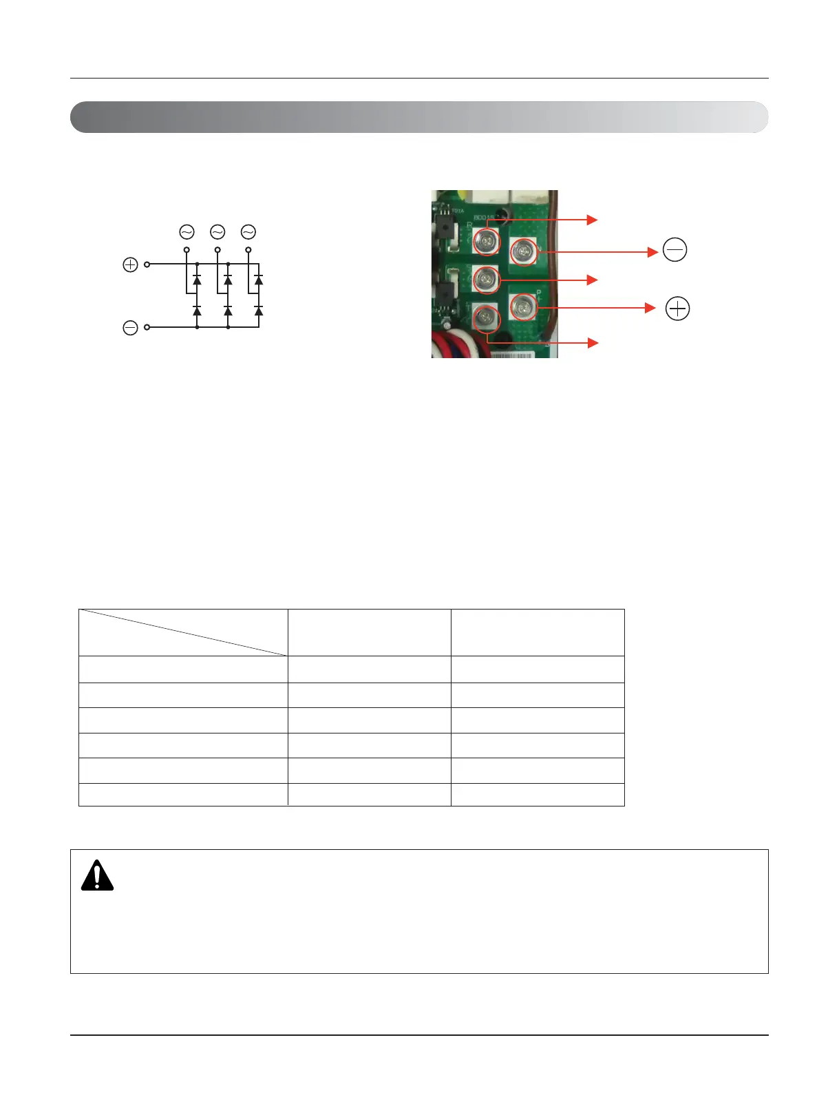
.2.4 Phase Bridge Diode Checking Method
1. Wait until Comp PCB DC voltage gets discharged, after the main power switch off.
2. Pull out DC_Link connector, CN COIL 1, 2 connector connected with Converter PCB.
3. Set multi tester in diode mode.
4. Measured value should be 0.4~0.7V measuring as below table.
5. In case the measured value is different from the table, set multi tester to resistance mode and measure. If the
value is small (0 Ω) or high (hundreds M Ω), PCB needs to be replaced.
6. In case that bridge diode is damaged, check if Comp, Converter PCB assembly(IPM) is needed to be replaced.
] Red(+) and black(-) are the measuring terminals of multi tester.
Internal circuit diagram Appearance
R(~) : red(+) 0.4 V ~ 0.7 V -
S(~) : red(+) 0.4 V ~ 0.7 V -
T(~) : red(+) 0.4 V ~ 0.7 V -
R(~) : black(-) - 0.4 V ~ 0.7 V
S(~) : black(-) - 0.4 V ~ 0.7 V
T(~) : black(-) - 0.4 V ~ 0.7 V
Diode terminal
+ terminal: black(-) - terminal: red(+)
Tester terminal
CAUTION
• Check the electric parts of c/box, 10 minutes after switching off the main supply and checking DC
voltage is discharged. Otherwise, there is chance of getting electric shock.
• There is chance of electric shock by charged voltage.
Checking Method for Key Components
 Loading...

