- 63 -
Copyright ©2013 LG Electronics. Inc. All right reserved.
Only for training and service purposes
LGE Internal Use Only
2.5 Inverter IPM/IGBT Checking Method
1. Wait until Comp PCB DC voltage is discharged after main power off.
2. Pull out DC_Link connector and U,V,W COMP connector connected with fan Comp PCB
3. Set multi tester to resistance mode.
4. If the value between P and N terminal of IPM is short(0Ω) or open(hundreds MΩ), PCB needs to be
replaced.(IPM damaged)
5. In the measured value with resistance mode should be within 2.3K Ω ±10%(25℃).
6. In case measured value is different from the table, PCB needs to be replaced.(PCB damaged).
] Red(+) and black(-) are the measuring terminals of multi tester.
P terminal : black (-) N terminal : red (-)
U terminal : red(+) 2.3K Ω ± 10%(25℃) 3.0K Ω ± 10%(25℃)
V terminal : red(+) 2.3K Ω ± 10%(25℃) 3.0K Ω ± 10%(25℃)
W terminal : red(+) 2.3K Ω ± 10%(25℃) 3.0K Ω ± 10%(25℃)
P terminal : red(+) N terminal : red (+)
U terminal : black(-) 3.0K Ω ± 10%(25℃) 2.3K Ω ± 10%(25℃)
V terminal : black(-) 3.0K Ω ± 10%(25℃) 2.3K Ω ± 10%(25℃)
W terminal : black(-) 3.0K Ω ± 10%(25℃) 2.3K Ω ± 10%(25℃)
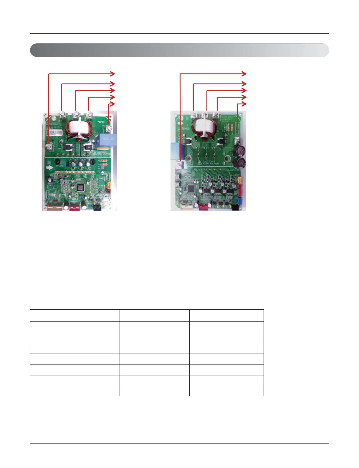
P terminal
U terminal
N terminal
V terminal
W terminal
P terminal
W terminal
N terminal
V terminal
U terminal
Inverter PCB IPM(8, 18, 20 HP)
Inverter PCB IGBT(10~16 HP)
 Loading...

