Removal Area for Liquid/Gas pipe
bottom side connections.
CAUTION
• Do not give damage to the pipe/base during the Knock Out
work.
• Proceed to pipe work after removing burr after Knock Out work.
• Perform sleeve work to prevent damage to the wire when con-
necting wires using knock Outs.
!
Remove leakage prevention cap
• Remove the leakage prevention cap attached to the outdoor unit
service valve before pipe work.
• Proceed the leakage prevention cap removal as follows:
- Verify whether the liquid/gas pipes are locked.
- Extract remaining refrigerant or air inside using the service port.
- Remove the leakage prevention cap
Leakage Prevention Cap
Low Pressure Gas pipe
Service Port
Refrigerant Charging Port
Liquid pipe
High Pressure Gas pipe
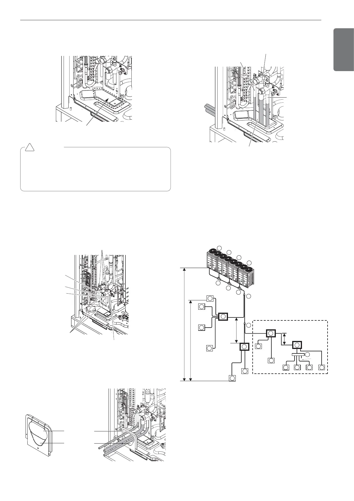
Pipe Drawing Out during Single / Series connection
Method of drawing out pipes on the front side
- Proceed with the pipe work as shown in the below figure for front
side pipe drawing out.
Pipe Knock Out
for High Pressure
Gas pipe
Pipe Knock Out for
Liquid/Gas pipes
Method of drawing out pipes on the bottom side
- Drawing out common pipe through side panel
Liquid pipe
Low Pressure Gas pipe
High Pressure
Gas pipe
Remove pipe knock out
Refrigerant piping system
3 Outdoor Units
Example : 12 Indoor Units connected
Ⓐ : Outdoor Unit
Ⓑ : Y branch
Ⓒ : Indoor Unit
Ⓓ : Connection branch pipe between Outdoor units : ARCNB21
Ⓔ : Connection branch pipe between Outdoor units : ARCNB31
Ⓕ : Connection branch pipe between Outdoor units : ARCNB41
Ⓖ : Header
Ⓗ : HR Unit
- Case 1 ("a") : Maximum height is 15m if you install with Y branch.
- Case 2 ("b") : Maximum height is 5m in serial connection of HR units.
A2
H1
C
1
2
C
C
C
3
4
E
F
D
A
F3
C1
B
C2
C3
*
B1
B2
A3
A4
a
b
c
d
e
g
j
k
x
l
m
n
sealing
f
i
H
h
"a"
"b"
F2
F1
H2
H4
G
H3
Slave 1
Slave 2
Slave 3
ODU Capacity
Master ≥ Slave1 ≥ Slave 2
C
5
C
6
C
7
C
8
C
10
C
9
C
11
C
12
A1
Master
Conditional
To satisfy below condition to make 40 m ~ 90 m of pipe length after first branch.
1) Diameter of pipes between first branch and the last branch should be in-
creased by one step, except pipe diameter B,C3 is same as Diameter A
Ø6.35 ’ Ø 9.52 ’ Ø 12.7 ’ Ø 15.88 ’ Ø 19.05 ’ Ø 22.2 ’ Ø 25.4*, Ø 28.58 ’
Ø 31.8*, Ø 34.9 ’ Ø 38.1*
* : It is not necessary to size up.
2) While calculating whole refrigerant pipe length, pipe B,C3 length should
be calculated twice.
A + B x 2 + C3 x 2 + C1 + C2 + a + b + c + d + e + f + g + i + j + k + l + m + n ≤ 1,000 m
3) Length of pipe from each indoor unit to the HR Unit
(a,b,c,d,e,f,g,i,j,k,l,m,n) ≤ 40 m
4)
[Length of pipe from outdoor unit to the farthest indoor unit D12 (A+B+C+D+e)]
-
[Length of pipe outdoor unit to the closest indoor unit D1(C1+a)] ≤ 40 m
Preparation Work
- Use Knock Outs of Base Pan of the outdoor unit for Left/Right or
Bottom pipe drawing outs.
 Loading...

