Switch for setup of HR Unit
Main function of SW02M
1. Selection of the method for addressing valves of an HR unit
(Auto/Manual)
2. Setting the zoning control
ON
S/W
Selection
No.1
Method for addressing valves of an HR
unit (Auto/Manual)
No.2 Model of HR unit
No.3 Model of HR unit
No.4 Model of HR unit
No.5 Valve group setting
No.6 Valve group setting
No.7
Use only in factory pro-
duction (preset to “OFF”)
Zoning set-
ting (“ON”)
No.8
Use only in factory pro-
duction (preset to “OFF”)
Turn the dip switch of
the zoning branch on.
Ex) Branch 1,2 are zon-
ing control.
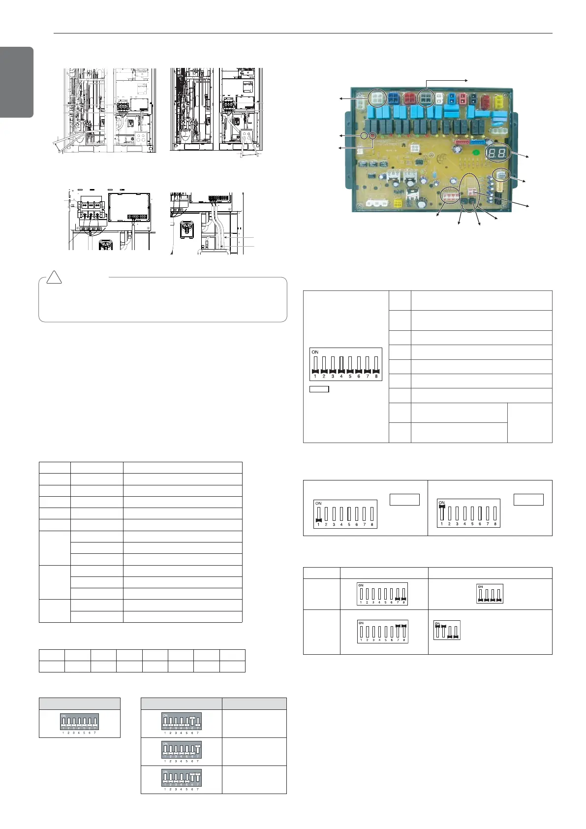
HR Unit PCB
28
ENGLISH
CAUTION
It should be wiring power cables or communication cables to avoid
interference with the oil level sensor. Otherwise, That oil level sensor
would be operated abnormally.
!
Front Side 1 Front Side 2
Main Power Connection Communication Connection
Checking the setting of outdoor units
Checking according to dip switch setting
- You can check the setting values of the Master outdoor unit from the
7 segment LED.
The dip switch setting should be changed when the power is OFF.
Checking the initial display
The number is sequentially appeared at the 7 segment in 5 seconds
after applying the power. This number represents the setting condition.
• Initial display order
• Example) ARUB620DTE4
• Master Unit • Slave Unit
Dip switch setting Dip switch setting ODU Setting
Slave 1
Slave 2
Slave 3
Order No Mean
①
8~20 Master model capacity
②
10~20 Slave 1 model capacity
③
10~20 Slave 2 model capacity
④
10~20 Slave 3 model capacity
⑤
8~80 Total capacity
⑥
1 Cooling Only
2 Heat Pump
3 Heat Recovery
⑦
38 380V model
46 460V model
22 220V model
⑧
1 Full function
2 Core function
① ② ③ ④ ⑤ ⑥ ⑦ ⑧
18 16 14 14 62 3 46 1
 Loading...

