21
ENGLISH
• Header should be insulated with the insulator in each kit.
• Joints between branch and pipe should be sealed with the tape in-
cluded in each kit.
• Any cap pipe should be insulated using the insulator provided with
each kit and then taped as described above.
Insulate the header using
the insulation
material attached to the
branch pipe kit
as shown in the figure.
Insulator
Insulator of field pipe
Tape
Tape
Cap pipe
Insulator for cap pipe
Y branch pipe
Models Gas pipe Liquid pipe
ARBLN
01621
I.D19.05
O.D15.88
I.D12. 7
I.D15.88
I.D12. 7
I.D15.88
I.D15.88
I.D12. 7
292
281
74
70
I.D12. 7
O.D9.52
I.D6.35
I.D9.52
I.D.9.52
I.D.6.35
I.D9.52
I.D.6.35
292
281
74
70
1
1
I.D25.4
413
390
83
I.D15.88
I.D19.05
I.D12. 7
I.D12. 7I.D19.05I.D15.88I.D19.0 5I.D22.2
I.D28.58
O.D25.4
I.D22.2
O.D19.05
O.D19.05
I.D22.2
I.D25.4
70 80 11 0
1
2
3
3 1 2
70
I.D9.52
I.D12. 7
53.6D.I25.9D.I
I.D9.52
I.D12. 7
I.D6.35
I.D12. 7
332
321
74
ID1905
376
404
96
I.D34.9
O.D31. 8
I.D22.2
O.D22.2
I.D28.58
I.D31. 8
O.D19.05
I.D28.58
120 90 12 0
I.D31. 8
2.22D.I85.82D.I
I.D19.05
I.D15.88
I.D12. 7
I.D19.05
I.D15.88
2
3
1
2
1 3
25.9D.I25.9D.I7.21D.O
I.D15.88 I.D19.05
I.D12. 7
I.D12. 7
I.D19.05
I.D15.88I.D12. 7
I.D19.05
O.D12. 7I.D6.35
I.D15.88
371
394
83
11 0 70
2
3
3 2
120 90 12 0
471
517
125
120 13 0
I.D19.05
I.D15.88
I.D12. 7
I.D19.05
I.D22.2
I.D41. 3 I.D38.1
I.D41. 3
O.D34.9
I.D34.9
I.D34.9
I.D22.2
I.D28.58
I.D28.58I.D38.1
I.D41. 3
I.D34.9
I.D38.1
O.D22.2
O.D38.1
O.D15.88
O.D28.58
90
2
3
3
3
2
2
3
416
444
96
O.D15.88 I.D9.52
I.D12. 7
O.D12. 7 I.D6.35
I.D9.52
I.D15.88 I.D19.05
I.D22.2
I.D22.2
I.D19.05
I.D15.88
I.D12. 7
I.D15.88
I.D19.05
I.D22.2
O.D19.0 5
80
11 0 11 0
2
3
1
2 3 3
O.D.28.58
I.D.22.2
115
X2
100
O.D15.88
I.D12.7
70
O.D.22.2
I.D.15.88I.D.19.05
120
O.D.38.1
I.D.34.9
I.D.28.58 O.D.44.48
X2
175
I.D31.8 I.D.53.98 I.D.25.4
I.D.44.48
I.D.44.48
I.D38.1I.D41.3
I.D.44.48
I.D38.1I.D41.3
I.D.53.98
420
490
134
1
2
3
32
3 3
3
3
2
O.D.19.05 I.D.12.7
I.D.15.88
O.D12.7 I.D6.35
I.D9.52
X2
110 110
I.D25.4 I.D22.2
I.D.19.05
I.D.19.05I.D.22.2
I.D.25.4
I.D.25.4
I.D.22.2
346
379
96
2
3 32
3
[unit:mm]
[unit:mm]
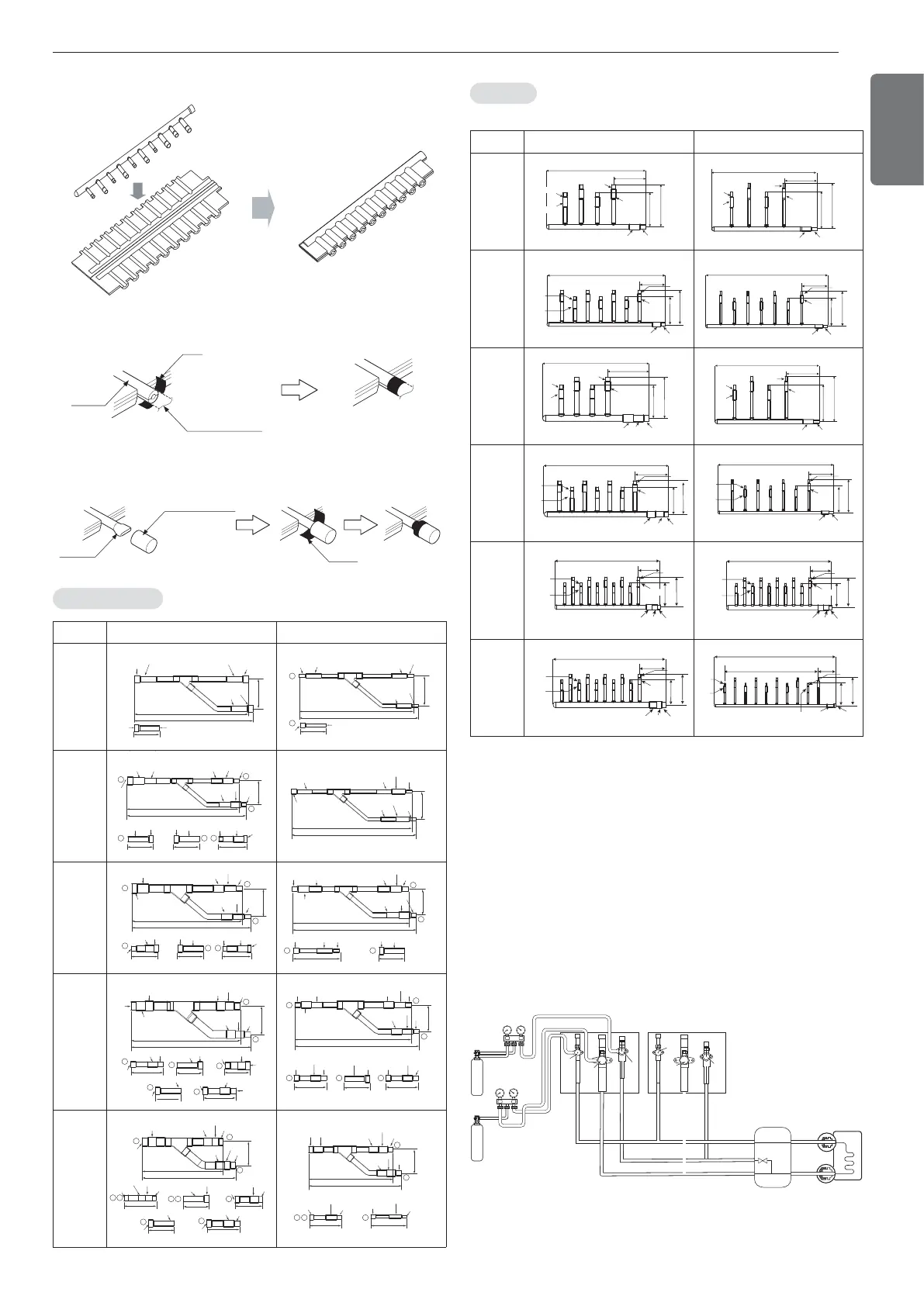
Leak test
Leak test should be made by pressurizing nitrogen gas to 3.8
MPa(38.7kgf/cm
2
). If the pressure does not drop for 24 hours, the sys-
tem passes the test. If the pressure drops, check where the nitrogen
leaks. For the test method, refer to the following figure. (Make a test
with the service valves closed. Be also sure to pressurize liquid pipe,
gas pipe and high pressure gas pipe)
The test result can be judged good if the pressure has not be reduced
after leaving for about one day after completion of nitrogen gas pres-
surization.
Indoor unit
Nitrogen gas
cylinder
Nitrogen gas
cylinder
Slave 1 outdoor unit Master outdoor unit
High Pressure Gas pipe
Liquide pipe
Low Pressure Gas pipe
High Pressure Gas pipe
Liquide pipe
Low Pressure Gas pipe
Liquid side
Gas side
Close
Close
Close
Close
Close
Close
HR unit
Leak Test and Vacuum drying
Header
Models Gas pipe Liquid pipe
4 branch
ARBL054
120
150
360
120
ID15.88
ID12.7
ID12.7
ID15.88
ID15.88
ID19.05
120
120
150
360
ID9.52
ID9.52
ID6.35
ID6.35
ID9.52
ID12.7
540
ID15.88
ID19.05
120
150
120
ID15.88
ID12.7
ID15.88
ID12.7
ID15.88
ID19.05
540
ID9.52
ID12.7
120
150
120
ID6.35
ID9.52
ID9.52
ID12.7
120
150
400
160
ID15.88
ID12.7
ID19.05
ID15.88
ID22.2
ID28.58 ID25.4
120
120
150
360
ID9.52
ID9.52
ID6.35
ID6.35
ID9.52
ID12.7
120
150
160
580
ID19.05
ID15.88
ID15.88
ID12.7
ID22.2ID28.58 ID25.4
120
150
700
120
ID6.35
ID9.52
ID9.52
ID6.35
ID9.52ID12.7
120
150
160
760
ID19.05
ID15.88
ID15.88
ID12.7
ID22.2ID28.58 ID25.4
120
150
160
760
ID19.05
ID15.88
ID15.88
ID12.7
ID22.2ID28.58 ID25.4
120
150
182
775
ID19.05
ID15.88
ID15.88
ID12.7
ID28.58
ID31.8 ID34.9
120
150
107
60*9=540
700
ID6.35
ID9.52
ID19.05ID15.88
ID9.52
ID6.35
 Loading...

