17
ENGLISH
1 inch or
3/4 inch
socket
Cover
Micro-switch
Adjustment screw
Vibration plate
Bellows
Pad
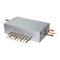
Installation of flow switch
• The flow switch must be installed at the horizontal pipe of the heat
water supply outlet of the product and check the direction of the heat
water flow before the installation. (Picture 1)
• When connecting the flow switch to the product, remove the jump
wire to connect to the communication terminal (5(A) and 5(B)) of the
outdoor unit control box. (Picture 2, 3) (Open the cover of the flow
switch and check the wiring diagram before connecting the wires.
The wiring method can differ by the manufacturer of the flow
switch.)
• If necessary, adjust the flow rate detection screw after consulting
with an expert and adjust to the minimum flow rate range. (Picture 4)
(Adjust the flow switch to touch the contact point when the flow rate
reaches minimum flow rate.)
- Minimum flow rate : 6 TON-17.8 GPM, 8 TON-17.8 GPM, 10 TON-
17.8 GPM, 12 TON-17.8 GPM, 16 TON-25.4 GPM
Picture 1 Picture 2
Picture 3
Picture 4
CAUTION
!
• If the set value does not satisfy the minimum flow rate or if the
set value is changed by the user arbitrarily, it can result in
product performance deterioration or serious product problem.
• If the product is operated with the heat water supply not
flowing smoothly, it can damage the heat exchanger or cause
serious product problems.
• In case of CH24 or CH180 error, there is a possibility that the
plate type heat exchanger is partially frozen inside. In this case
resolve the issue of partial freezing and then operate the
product again. (Cause of partial freezing : Insufficient heat water
flux, water not supplied, insufficient coolant, alien particle
penetrated inside plate type heat exchanger)
• When the product operates while the flow switch touches the
contact point at the flow rate range out of the permitted range,
it can cause product performance deterioration or serious
product problem.
• Must use the normal closed type flow switch
- Circuit of outdoor unit is normal closed type.
Flow switch work
• You must install the flow switch to the water collection pipe system
connecting to the outdoor unit.
(Flow switch acts as the 1st protection device when the heat water
is not supplied. If a certain level of water does not flow after
installing the flow switch, an error sign of CH 189 error will be
displayed on the product and the product will stop operating.)
• When setting the flow switch, it is recommended to use the product
with default set value to satisfy the minimum flow rate of this
product. (The minimum flow rate : 6 TON-17.8 GPM, 8 TON-17.8
GPM, 10 TON-17.8 GPM, 12 TON-17.8 GPM, 16 TON-25.4 GPM)
• Select the flow switch with the permitted pressure specification
considering the pressure specification of the heat water supply
system. (Control signal from outdoor unit is AC 220 V.)
PIPE CONNECTIONS BETWEEN
INDOOR AND OUTDOOR UNIT
- Pipe connections can be done on the front side or on the side
according to the installation environments.
- Be sure to let 0.2 kgf/cm
2
(2.8 psi) Nitrogen flow in the pipe when
welding.
- If Nitrogen was not flown during welding, many oxidized membranes
may form inside the pipe and disturb the normal operations of valves
and condensers.
Refrigerant piping system
3 Outdoor Units
Example : 12 Indoor Units connected
Ⓐ : Outdoor Unit
Ⓑ : Y branch
Ⓓ : Indoor Unit
Ⓔ : Connection branch pipe between Outdoor units : ARCNB31
Ⓕ : Connection branch pipe between Outdoor units : ARCNB21
Ⓗ : Header
Ⓘ : HR Unit
- Case 1 ("a") : Maximum height is 15 m(49.2 ft) if you install with Y
branch.
- Case 2 ("b") : Maximum height is 5 m(16 ft) in serial connection of HR
units.
A1
I1
D
1
0
m
or l
e
s
s
1
2
D
D
D
3
4
A
C1
B
C2
C3
*
B1
B2
A2
A3
a
b
c
d
e
g
j
k
D
x
l
m
n
sealing
f
i
H
h
"a"
"b"
E
F
I2
I4
H
I3
Master
Slave 1
Slave 2
ODU Capacity
Master ≥ Slave1 ≥ Slave 2
D
5
D
6
D
7
D
8
D
10
D
9
D
11
D
12
ʺ
ʻ
Refrigerant Pipe
Regulator
Nitrogen
Taping
Valve
Nitrogen
Direction
Nitrogen
Direction
For Heat Recovery System Installation
WARNING
!
• Piping length from outdoor unit branch to outdoor unit ≤ 10 m
(32.8 ft), equivalent length : max 13 m (42.7 ft) (for 12 Ton (144
kBtu) or more)
* If the large capacity indoor units (Over 48 kBtu; using over
Ø 15.88 (5/8) / Ø 9.52 (3/8)) are installed, it should be used the
Valve Group setting.

 Loading...