EasyManua.ls Logo

LG Multi V Series - Piping Diagrams

LG Multi V Series
11 pages
Print Icon
To Next Page IconTo Next Page
To Previous Page IconTo Previous Page
Loading...
- 5 -
Copyright ©2009 LG Electronics. Inc. All right reserved.
Only for training and service purposes
LGE Internal Use Only
3. Piping Diagrams
Heat Exchanger
C.F.F
lndoor unit
EEV
:Heating
:Cooling
Filter
Filter
Th3
Th2
Th1
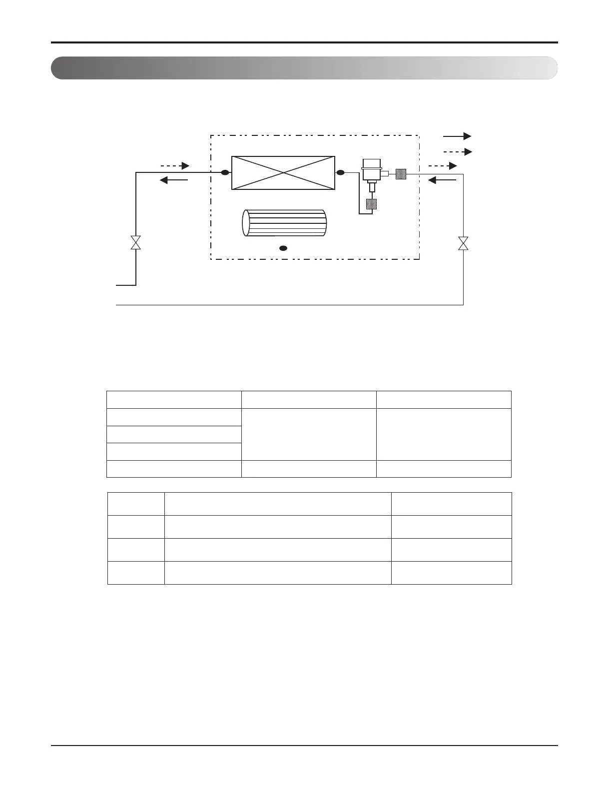
Refrigerant pipe connection port diameter
[unit: mm(inch)]
LOC. Description PCB Connector (Color)
Th1 Thermistor for room air temperature CN-ROOM (Yellow)
Th2 Thermistor for pipe in temperature CN-PIPE_IN (White)
Th3 Thermistor for pipe out temperature CN-PIPE_OUT (Red)
Model Gas Liquid
ARNU09GTL*4
Ø12.7(1/2) Ø6.33(1/4)ARNU12GTL*4
ARNU18GTL*4
ARNU24GTL*4 Ø15.88(5/8) Ø9.52(3/8)

Other manuals for LG Multi V Series

Related product manuals