6
INSTALLATION LAYOUT
ENGLISH
RA
ῧ-1
Ῡ-1
Ὺ
Ῡ-2
ῧ-2
ῡ
ῤ
ῦ
ῥ
ῢ
Ύ
Ῠ-1 Ῠ-2
EA OA SA
Power cable
Communication cable
Thermistor signal
Temperature /
humidity sensor
MCC
No. Item Applied Standards
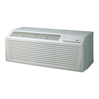
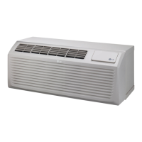
①
AHU -
②
AHU CONTROL KIT PAHCNM000
③
Expansion kit -
④
Outdoor unit MULTI V
⑤
Pipe in Thermistor(Liquid)
Sensor : Ø 5(NTC 5 kΩ), Length : 5 m, Cable color : Black
⑥
Pipe out Thermistor(Gas)
Sensor : Ø 7(NTC 5 kΩ), Length : 5 m, Cable color : Red
⑦-1, 2
Temperature/humidity sensor RA, SA Optional
⑧-1, 2
Ventilation Fan, Supply Fan -
⑨-1, 2
Inverter drive kit -
⑩
Main power switch board MCC switch board panel
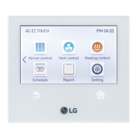
⑪
HMI -
Caution on installation layout
- MCC is part of the installation construction to be performed by the equipment supplier, so
confer with the supplier before installing the product.
- Temperature/humidity sensors must be installed on the SA (supply)/RA(ventilation) ducts before
the product can run normally.
INSTALLATION LAYOUT
Installation composition diagram
 Loading...