EasyManua.ls Logo

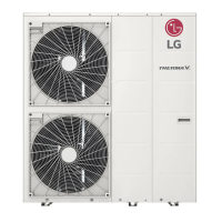
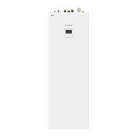
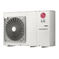
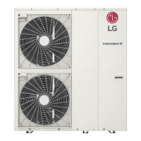
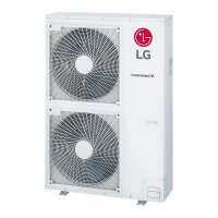
LG Therma V HM091MRS User Manual

LG Therma V HM091MRS
165 pages
To Next Page IconTo Next Page
Page #1 background imageLoading...
Page #1 background image
INSTALLATION MANUAL
AIR-TO-WATER
HEAT PUMP
www.lg.com
Copyright © 2018 - 2021 LG Electronics Inc. All Rights Reserved.
MFL68026607
Rev.08_042221
Please read this installation manual completely before installing the product.
Installation work must be performed in accordance with the national
wiring standards by authorized personnel only. Please retain this
installation manual for future reference after reading it thoroughly.
Original instruction
[EU Representative]
LG Electronics Inc. EU Representative : LG Electronics European Shared Service Center B.V.
Krijgsman 1, 1186 DM Amstelveen, The Netherlands
[
Manufacturer
] LG Electronics Inc. Changwon 2nd factory 84, Wanam-ro, Seongsan-gu, Changwon-si, Gyeongsangnam-do, KOREA
PORTUGUÊS
MAGYAR
БЪЛГАРСКИ
SRPSKI
HRVATSKI
SLOVENŠČINA
DANSK
ENGLISH
ITALIANO
ESPAÑOL
FRANÇAIS
DEUTSCH
ΕΛΛΗΝΙΚΆ
ČEŠTINA
NEDERLANDS
POLSKI
LIMBA ROMÂNĂ
Table of Contents

Questions and Answers:

LG Therma V HM091MRS Specifications

General IconGeneral
TypeAir to Water Heat Pump
ModelHM091MRS
Heating Capacity9.0 kW
Energy Efficiency Class HeatingA++
RefrigerantR32
Cooling Capacity8 kW
Power Supply220-240 V, 50 Hz

Summary

Preface

Safety Instructions

Installation Part

General Information

Model Information

Details on product model naming conventions and specifications.

Model name and related information

Table listing model names, capacities, and power sources.

Parts and Dimensions

Identifies and illustrates the main parts and dimensions of the unit.

Control Parts

Diagrams and descriptions of the unit's control box components.

Remote Controller

Explanation of the remote controller's display and buttons.

Typical Installation Example

Illustrates conceptual installation scenarios for heating and cooling.

Cycle Diagram

Visual representation of the refrigerant and water cycles within the unit.

Water cycle

Schematic diagram showing the water flow for basic and advanced installations.

Installation

Transporting the Unit

Guidelines for safely lifting and moving the unit during installation.

Installation places

Recommendations for selecting an optimal and safe location for the unit.

Installation at Seaside

Specific considerations for installing the unit near coastal areas.

Seasonal Wind and Cautions in Winter

Precautions for operating the unit in areas with heavy snow or cold weather.

Foundation for Installation

Instructions for preparing a stable and level foundation for the unit.

Electrical Wiring

Requirements and warnings for connecting the unit's electrical supply.

Wiring of main power supply and equipment capacity

Guidance on selecting appropriate power supply and cable specifications.

Water Piping and Water Circuit Connection

Steps and considerations for connecting the unit's water pipes.

Water Charging

Procedures for filling the system with water and purging air.

Pipe Insulation

Importance and purpose of insulating water pipes for efficiency and protection.

Water pump Capacity

Information on setting the water pump's variable capacity for optimal performance.

Pressure Drop

Considerations for pressure loss in the system and pump selection.

Performance curve

Charts showing pump performance based on flow rate and head.

Water Quality

Requirements for water quality in the heating system.

Frost protection

Instructions for using antifreeze solutions to prevent freezing.

Water Volume and Expansion Vessel Pressure

Guidance on adjusting expansion vessel pre-pressure based on water volume.

Accessories Installation

Accessories supported by LG Electronics

List of compatible accessories and their models from LG.

Accessories supported by 3rd party Companies

List of compatible accessories and their specifications from third parties.

Before Installation

General precautions and warnings before installing any accessory.

Thermostat

Information on thermostat types, installation conditions, and placement.

2nd Circuit

Guidance on setting up a second heating/cooling circuit with a Mix Kit.

3rd Party Boiler

Instructions for connecting and controlling an auxiliary boiler.

3rd Party Controller

How to connect external controllers using Modbus protocol.

Meter Interface

Installation of a module to monitor energy and power generation.

Central Controller

Methods for installing the PI485 PCB for central control.

Remote Controller

Instructions for mounting and wiring the wired remote controller.

DHW Tank

Considerations for installing a Domestic Hot Water tank and its components.

Solar Thermal Kit

Procedures for connecting the solar thermal kit for hot water heating.

Dry Contact

Installation of a switch for HVAC system automatic control.

External Controller - Setting up programmable digital input operation

Connecting an external controller for ON/OFF control via digital input.

Remote Temperature Sensor

Guidelines for installing a remote sensor to detect ambient temperature.

Solar pump

How to install a solar pump to energize water flow in the solar thermal system.

External pump

Installing an external pump for large rooms or insufficient insulation.

Wi-fi Modem

Installing a modem for remote system operation via smartphone.

Energy State

Information on available energy states for optimizing renewable energy usage.

Digital Input for energy saving (ESS, Smart Grid)

Setting up digital inputs for energy saving modes and smart grid integration.

2Way Valve

Wiring and installation of a 2-way valve for water flow control.

3Way Valve(A)

Installation and wiring of a 3-way valve for DHW tank or floor heating.

3Way Valve(B)

Installation and wiring of a 3-way valve for solar thermal system control.

Electric Heater

Instructions for piping and wiring the electric heater accessory.

Final check

A checklist of critical items before completing accessory installation.

Configuration

DIP Switch Setting

Instructions for setting DIP switches on the indoor PCB for system configuration.

DIP Switch Information

Details on the function and settings of Option Switch 2.

Option Switch 1

Configuration options for MODBUS and MODBUS Function.

Option Switch 3

Settings for Remote Air Sensor and Antifreeze solution usage.

Outdoor PCB General Information

Overview of the outdoor PCB and its DIP switch SW2.

Emergency Operation

Explanation of system troubles, classified troubles, and emergency modes.

Service Setting

How to enter service setting

Steps to access the service menu on the remote controller.

Service setting

Overview of available product service functions.

Service Contact

How to check and input service center contact information.

Model Information

How to view product and capacity information via the remote controller.

RMC Version Information

How to check the software version of the remote controller.

Open Source License

Accessing information about the open source software used.

Installer Setting

How to enter installer setting

Procedure to access the installer settings menu using a password.

Installer setting

A comprehensive list of installer-configurable functions and parameters.

3 Minutes Delay

Temporarily bypasses the 3-minute delay for outdoor unit components.

Select Temperature Sensor

Configuration for using air or water temperature sensors for control.

Dry Contact Mode

Setting the dry contact function for external control signals.

Air cooling set temp

Setting the temperature range for cooling based on air temperature.

Water heating set temp

Setting the temperature range for heating based on water temperature.

DHW set temp

Setting the target temperature for Domestic Hot Water.

Screed drying

Controls floor heating temperature for curing concrete structures.

Tank disinfection setting 1, 2

Configuring special modes for DHW tank disinfection against legionella.

Heater priority

Determining the priority between electric heater and DHW tank heater.

DHW time setting

Setting operation times, stop times, and delay times for DHW heating.

Seasonal auto temp

Setting operational reference values for Seasonal Auto mode.

Anti-freezing Temperature

Setting the temperature to prevent frostbite and system freezing.

Solar Thermal System

Setting operation reference values for the solar thermal system.

Energy state

Controlling product operation based on Energy Storage System (ESS) states.

Password Initialization

Resetting the remote controller password to its default value.

Commissioning

Check List before Starting Operation

Pre-operation checklist covering wiring, pressure, and installation checks.

Starting Operation

Steps and checks to perform before initiating the unit's first operation.

Check before Starting Operation

Verifying refrigerant leakage, power connection, and insulation resistance.

Starting Operation flow chart

A flowchart guiding the initial operational test sequence.

Airborne Noise Emission

Information on the unit's noise emission levels and exposure factors.

Vacuum & Charge of Refrigerant

Procedures for vacuuming the system and charging refrigerant.

1. Vacuum

Steps for performing the vacuum action on the refrigerant circuit.

2. Charge of refrigerant

Process for charging the correct amount of refrigerant into the system.

3. Location of SVC port

Identifying the Service Valve (SVC) ports on the unit.

How to drain remaining water in the product

Instructions for draining water from the unit to prevent freezing during storage.

Troubleshooting

Guidance for diagnosing and resolving operational issues and errors.

Troubleshooting for Problem while Operation

Common problems during operation and their solutions.

Troubleshooting for Error Code

A list of error codes, their causes, and corresponding check points.

Related product manuals