EasyManua.ls Logo

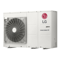
LG Therma V R32 User Manual

LG Therma V R32
39 pages
To Next Page IconTo Next Page
Page #1 background imageLoading...
Page #1 background image
R32 Monobloc - April 2020
Installation Instructions.
Therma V R32: Generation 3.

Other manuals for LG Therma V R32

Question and Answer IconNeed help?

Do you have a question about the LG Therma V R32 and is the answer not in the manual?

LG Therma V R32 Specifications

General IconGeneral
BrandLG
ModelTherma V R32
CategoryHeat Pump
LanguageEnglish

Summary

Outdoor Installation

Outdoor Installation – Bill of Materials.

Lists components for outdoor installation, including the LG controller packed within the heat pump.

Indoor Installation – Bill of Materials.

LG Tank Kit.

Details the components included in the LG Tank Kit for indoor installation.

Installation Schematic. Heating Only – 5, 7 & 9kW.

Installation Wiring. Heating Only – 5, 7, 9, 12, 14 & 16kW.

Installation Schematic. DHW & Heating with 1 Zone – 5, 7 & 9kW.

Installation Schematic. DHW & Heating with 2 Zone's – 5, 7 & 9kW.

Installation Wiring. DHW & Heating 5, 7, 9, 12, 14 & 16kW.

Installation Wiring. Boiler, DHW & Heating 5, 7, 9, 12, 14 & 16kW.

Installation – Mains Power Cable.

Installation – Terminal Block 1.

Honeywell 3 Way Valve(V4044c) – 2 Wire.

Explains the wiring and function of the Honeywell 3 Way Valve for Terminal Block 1.

Installation – Terminal Block 3.

230V 2 Pole Relay

Details the connection and use of a 230V 2 Pole Relay for Terminal Block 3.

Installation Wiring. R32 Monobloc – 1-Zone Control Schematic.

Installation – Antifreeze Solution Temp.

Central Controller.

DHW Installation.

DHW Installation – Tank Heater.

Describes the wiring connections for the DHW tank heater using the LG DHW Tank Kit.

Configuration - Dip Switches.

Antifreeze Logic – Dip switch 2 On(To the right)

Configuration for antifreeze logic via dip switch 2 on the main PCB.

DHW – Dip switch 3 On(To the right)

Configuration for DHW function via dip switch 3 on the main PCB.

Room Thermostat Control(Field Supplied)

Configuration for room thermostat control using dip switch 8 on the main PCB.

Configuration – Installer Settings.

Error Codes. CH14.

First two weeks: Blocked filters and/or air pockets

Explains CH14 error code causes during the first two weeks, related to filters and air pockets.
R32 Monobloc Therma V Commissioning Sheet - Heating system set up

Related product manuals