MULTI F OUTDOOR UNIT | 15
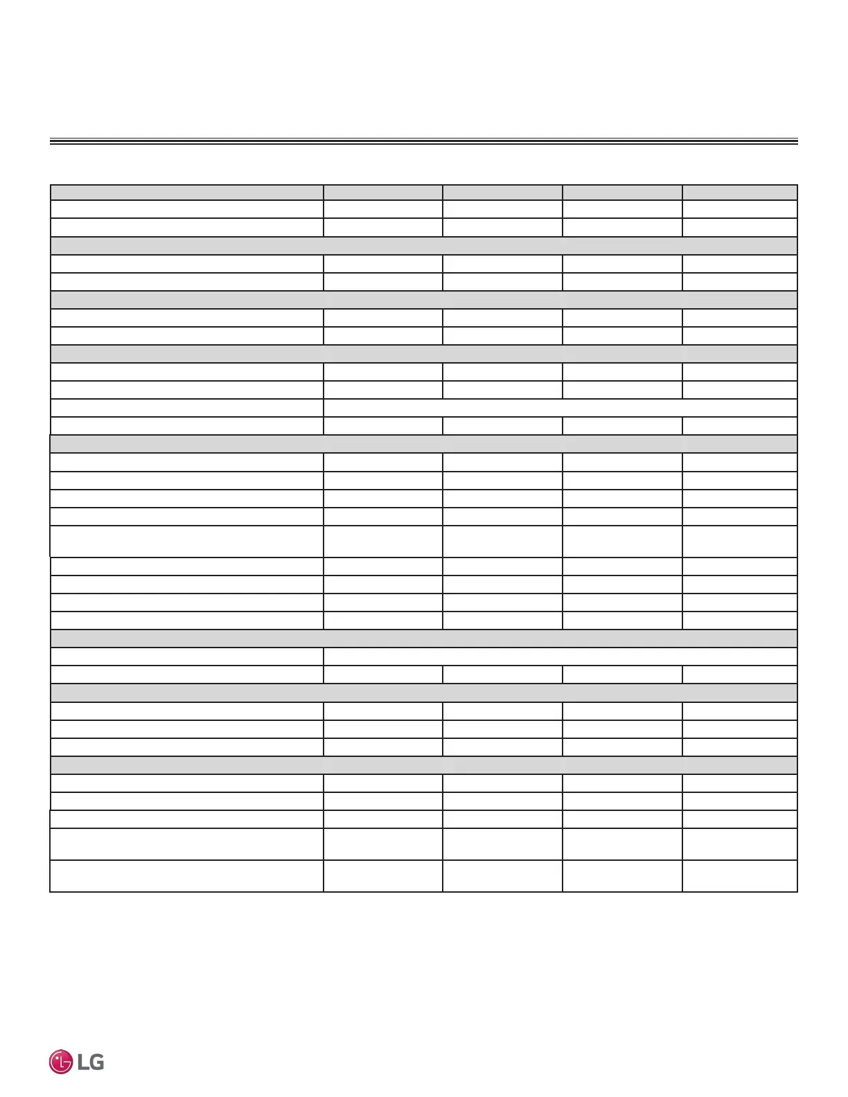
Multi F Outdoor Unit Data
'XHWRRXUSROLF\RIFRQWLQXRXVSURGXFWLQQRYDWLRQVRPHVSHFL¿FDWLRQVPD\FKDQJHZLWKRXWQRWL¿FDWLRQ
©/*(OHFWURQLFV86$,QF(QJOHZRRG&OLIIV1-$OOULJKWVUHVHUYHG³/*´LVDUHJLVWHUHGWUDGHPDUNRI/*&RUS
MULTI
F
MAX
MULTI
F
MULTI F OUTDOOR UNIT
General Data
Model Number
LMU180HV LMU18CHV LMU240HV LMU24CHV
Cooling Capacity (Btu/h)
1
(Min.~Rated~ Max.)
8,400~18,000~21,600 8,400~17,000~19,000 8,400~23,600~25,000 8,400~20,000~25,000
Heating Capacity (Btu/h)
1
(Min.~Rated~ Max.)
10,080~22,000~25,000 10,248~22,000~24,000 10,080~24,600~29,000 9,240~24,000~28,800
Operating Range
Cooling (°F DB)
14
7
to 118 14
7
to 118 14
7
to 118 14
7
to 118
Heating (°F WB)
-4 to +64 -4 to +64 -4 to +64 -4 to +64
Compressor
Inverter Quantity
Twin Rotary x 1 Twin Rotary x 1 Twin Rotary x 1 Twin Rotary x 1
Oil/Type
FVC68D FVC68D FVC68D FVC68D
Fan (Side Discharge)
Type
Propeller Propeller Propeller Propeller
Motor Output (W) x Qty.
85.4 x 1 85.4 x 1 85.4 x 1 85.4 x 1
Motor / Drive
Brushless Digitally Controlled / Direct
Maximum Air Volume (CFM)
1,766 1,766 1,766 1,766
Unit Data
Refrigerant Type
R410A R410A R410A R410A
Refrigerant Control/Location
EEV / Outdoor Unit EEV / Outdoor Unit EEV / Outdoor Unit EEV / Outdoor Unit
Min. Number Indoor Units / System
2
2222
Max. Number Indoor Units / System
2
2233
Maximum Allowable Total Indoor Unit Connected
Capacity (Btu/h)
24,000 24,000 33,000 33,000
Sound Pressure (Cooling / Heating) dB(A)
3
49 / 54 49 / 52 50 / 54 49 / 52
Net Unit Weight (lbs.)
101 100 101.4 100
Shipping Weight (lbs.)
109.8 108 110.2 108
Power Wiring / Communications Cable (No. x AWG)
4,5
4C x 14 4C x 14 4C x 14 4C x 14
Heat Exchanger
Material and Fin Coating
Copper Tube/Aluminum Fin and GoldFin™/Hydrophilic
Rows / Columns/Fins per inch x Qty.
(2 x 28 x 14) x 1 (2 x 28 x 14) x 1 (2 x 28 x 14) x 1 (2 x 28 x 14) x 1
Piping
Liquid Line Connection (in., OD) x Qty.
1/4 x 2 1/4 x 2 1/4 x 3 1/4 x 3
Vapor Line Connection (in., OD) x Qty.
3/8 x 2 3/8 x 2 3/8 x 3 3/8 x 3
Factory Charge lbs. of R410A
3.97 3.96 3.97 3.96
Piping Lengths
Maximum Total Piping (ft.)
6
164.0 164.0 230.0 246.1
Maximum Outdoor Unit to Indoor Unit Piping (ft)
82.0 82.0 82.0 82.0
Piping Length (No Additional Refrigerant [ft])
98.4 49.2 98.4 73.8
Maximum Elevation between Outdoor Unit and
Indoor Unit (ft.)
49.2 49.2 49.2 49.2
Maximum Elevation between Indoor Unit and
Indoor Unit (ft.)
24.6 24.6 24.6 24.6
Table 7: 0XOWL)2XWGRRU8QLW6SHFL¿FDWLRQV
1
Rated capacity applied with non-ducted indoor units, and is rated 0 ft. above sea level with 25 ft.
of refrigerant line per indoor unit and a 0 ft. level difference between outdoor and indoor units. All
capacities are net with a combination ratio between 95 – 105%.
Rated cooling capacity obtained with air entering the indoor unit at 80ºF dry bulb (DB) and 67ºF wet
bulb (WB) and outdoor ambient conditions of 95ºF dry bulb (DB) and 75ºF wet bulb (WB).
Rated heating capacity obtained with air entering the indoor unit at 70ºF dry bulb (DB) and 60ºF wet
bulb (WB) and outdoor ambient conditions of 47ºF dry bulb (DB) and 43ºF wet bulb (WB).
2
At least two indoor units must be connected. For allocated capacity information, see the combination
tables in the "Multi F / Multi F MAX Combination Data Manual" on www.lghvac.com. For performance
data, see "Multi F / Multi F MAX Performance Data Manual" on www.lghvac.com.
3
Sound pressure levels are tested in an anechoic chamber under ISO Standard 3745 and are the same
in both cooling and heating mode. These values can increase due to ambient conditions during operation.
4
Power wiring to the outdoor unit is field supplied, solid or stranded, and must comply with the ap-
plicable local and national codes. For detailed information, please refer to electrical characteristics on
page 19.
5
All power wiring / communication cable to be minimum 14 AWG, 4-conductor from the outdoor unit to
the indoor units, stranded, shielded or unshielded (if shielded, it must be grounded to the chassis of
the outdoor unit only), and must comply with applicable local and national codes. For detailed electrical
information, please refer to electric characteristics on page 19.
6
Piping lengths are equivalent.
7
Installation of an optional Low Ambient Wind Baffle Kit will allow operation down to -4°F in cooling mode.
 Loading...