MULTI F MAX OUTDOOR UNIT
General Data
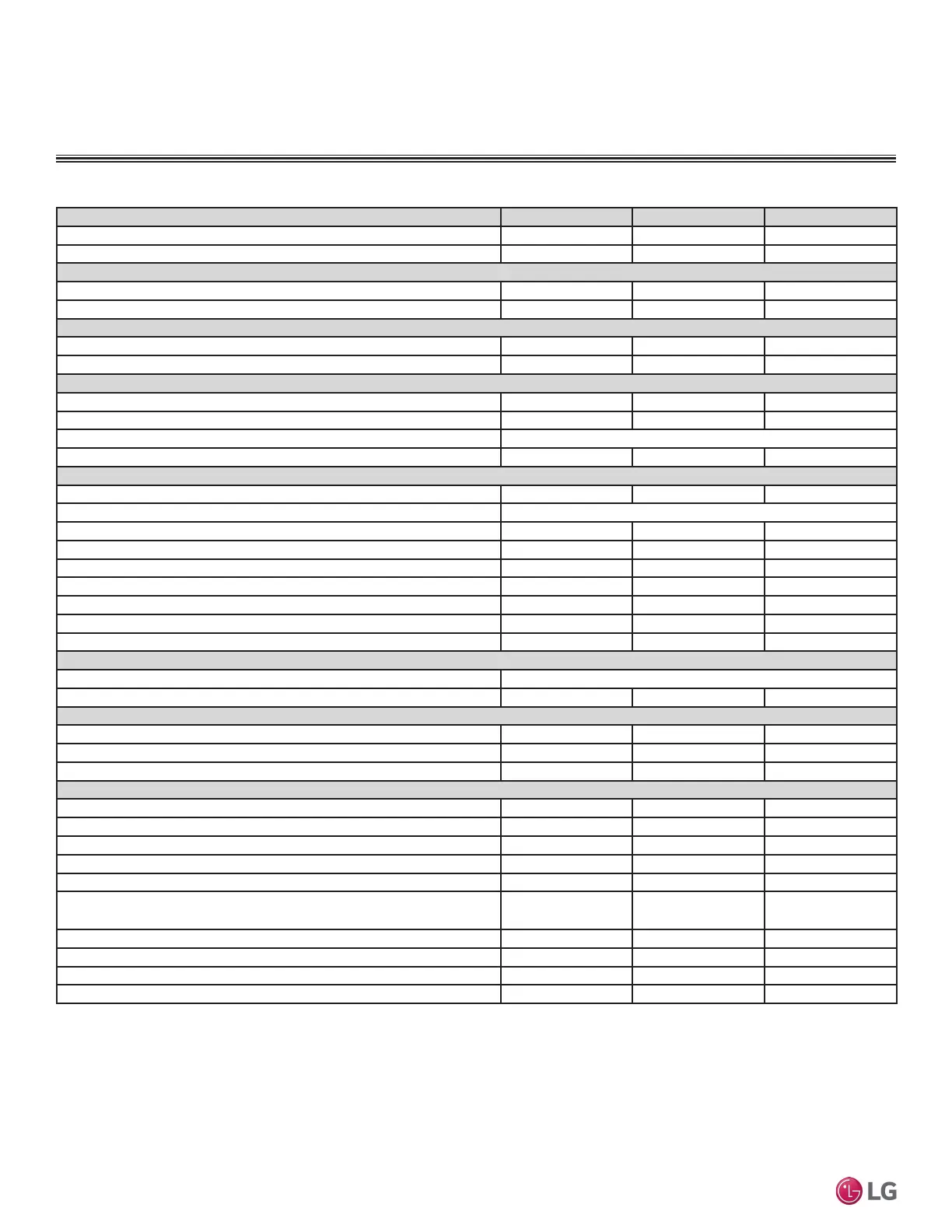
Table 22: Multi F MAX Outdoor Unit General Data.
Model Number
LMU480HV LMU540HV LMU600HV
Cooling Capacity (Btu/h) (Minimum ~ Rated ~ Maximum)
1
14,400~48,000~58,000 14,400~52,500~63,200 15,600~60,000~68,000
Heating Capacity (Btu/h)
(Minimum ~ Rated ~ Maximum)
1
15,840~54,000~61,000 16,272~58,000~64,000 17,940~64,000~70,000
Operating Range
Cooling (°F DB)
14
7
- 118 14
7
- 118 14
7
- 118
Heating (°F WB)
-4 - 64 -4 - 64 -4 - 64
Compressor
Inverter Quantity
Twin Rotary x 1 Twin Rotary x 1 Twin Rotary x 1
Oil/Type
FVC68D FVC68D FVC68D
Fan (Side Discharge)
Type
Propeller Propeller Propeller
Motor Output (W) x Qty.
124.2 x 2 124.2 x 2 124.2 x 2
Motor/Drive
Brushless Digitally Controlled/Direct
Maximum Air Volume (CFM)
2,119 x 2 2,119 x 2 2,119 x 2
Unit Data
Refrigerant Type
R410A R410A R410A
Refrigerant Control/Location
EEV / Outdoor Unit, Branch Distribution Unit
Min. Number Indoor Units/System
2
222
Max. Number Indoor Units/System
2
888
Maximum Allowable Total Indoor Unit Connected Capacity (Btu/h)
65,000 73,000 81,000
Sound Pressure ±3 dB(A)
3
(Cooling / Heating)
54 / 56 54 / 56 56 / 58
Net Unit Weight (lbs.)
214 214 223
Shipping Weight (lbs.)
236 236 249
Power/Communications Wiring Between ODU and BDU (No. X AWG)
4,5
4C x 14 4C x 14 4C x 14
Heat Exchanger
Material and Fin Coating
Copper Tube / Aluminum Fin and GoldFin™/Hydrophilic
Rows/Columns/Fins per inch x Qty.
(2 x 32 x 14) x 2 (2 x 32 x 14) x 2 (3 x 32 x 14) x 2
Piping
Liquid Line Connection (in., OD) x Qty.
3/8 x 1 3/8 x 1 3/8 x 1
Vapor Line Connection (in., OD) x Qty.
3/4 x 1 3/4 x 1 3/4 x 1
Factory Charge lbs. of R410A
9.7 9.7 12.3
Piping Lengths
Maximum Total System Piping (ft.)
6
475.7 475.7 475.7
Maximum Main Pipe Length (ODU to BDU [ft.])
180.4 180.4 180.4
Total Branch Piping (BDU to all IDUs [ft.])
295.3 295.3 295.3
Maximum Branch Pipe Length (Length between each BDU and IDU [ft.])
49.2 49.2 49.2
Maximum Outdoor Unit to Indoor Unit Pipe Length (ft.)
229.6 229.6 229.6
Piping Length (No Additional Refrigerant [ft.]; approx. 16 ft. of Main Piping +
131 ft. of Branch Piping)
147.6 147.6 147.6
Maximum Elevation between ODU and IDU (ft.)
98.4 98.4 98.4
Maximum Elevation between IDU and IDU (ft.)
49.2 49.2 49.2
Maximum Elevation between BDU and IDU (ft.)
32.8 32.8 32.8
Maximum Elevation between BDU and BDU (ft.)
49.2 49.2 49.2
1
Rated capacity applied with non-ducted indoor units, and is rated 0 ft. above sea level with a 0 ft. level differ-
ence between outdoor and indoor units. All capacities are net with a combination ratio between 95 – 105%.
Rated cooling capacity obtained with air entering the indoor unit at 80ºF dry bulb (DB) and 67ºF wet
bulb (WB) and outdoor ambient conditions of 95ºF dry bulb (DB) and 75ºF wet bulb (WB).
Rated heating capacity obtained with air entering the indoor unit at 70ºF dry bulb (DB) and 60ºF wet
bulb (WB) and outdoor ambient conditions of 47ºF dry bulb (DB) and 43ºF wet bulb (WB).
2
At least one Branch Distribution Unit is required for system operation; a maximum of two can be
installed per outdoor unit with use of Y-branch accessory (PMBL5620). At least two indoor units must
be connected. For allocated capacity information, see the combination tables in the “Multi F / Multi F
MAX Combination Data Manual” on www.lghvac.com. For performance data, see “Multi F / Multi F MAX
Performance Data Manual” on www.lghvac.com.
3
Sound pressure levels are tested in an anechoic chamber under ISO Standard 3745. These values can
increase due to ambient conditions during operation.
4
Power wiring to the outdoor unit is field supplied, solid or stranded, and must comply with the ap-
plicable local and national codes. For detailed information, please refer to electrical characteristics on
page 37.
5
All power wiring / communication cable to be minimum 14 AWG, 4-conductor from the outdoor unit to
the BD unit (Multi F MAX systems only), and 14 AWG, 4-conductor from the BD unit to the indoor unit,
stranded, shielded or unshielded (if shielded, it must be grounded to the chassis of the outdoor unit
only), and must comply with applicable local and national codes. For detailed electrical information,
please refer to electric characteristics on page 37.
6
Piping lengths are equivalent.
7
Installation of an optional Low Ambient Wind Baffle Kit will allow operation down to -4°F in cooling mode.
'XHWRRXUSROLF\RIFRQWLQXRXVSURGXFWLQQRYDWLRQVRPHVSHFL¿FDWLRQVPD\FKDQJHZLWKRXWQRWL¿FDWLRQ
©/*(OHFWURQLFV86$,QF(QJOHZRRG&OLIIV1-$OOULJKWVUHVHUYHG³/*´LVDUHJLVWHUHGWUDGHPDUNRI/*&RUS
36 | MULTI F MAX OUTDOOR UNIT
Multi F and Multi F MAX Heat Pump System Engineering Manual
MULTI
F
MAX
MULTI
F
 Loading...