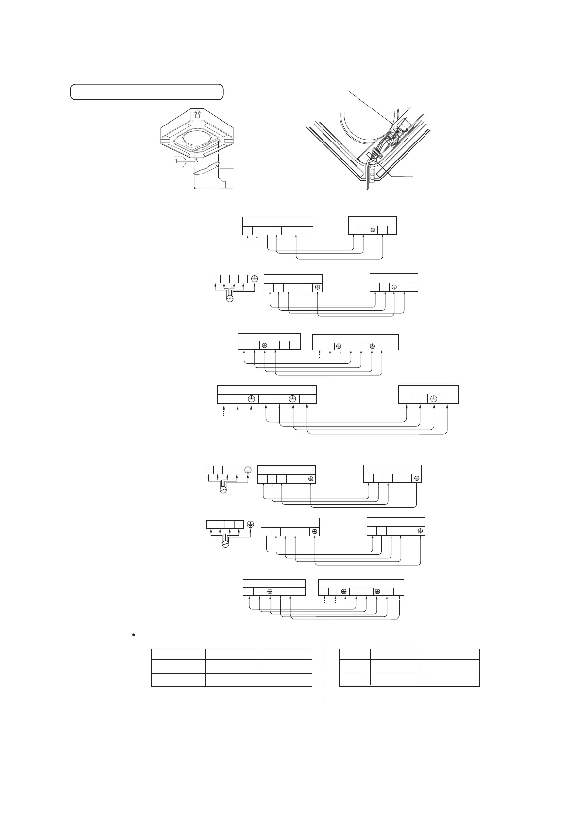
ELECTRICAL WIRING
Air Sunction Side Diagrams
.
Clamp
NT
SR
42k/48k
Power Cable Of Indoor Unit
Cable Of Controller
Cover Controller
Cover Controller Fisation Bolt (5set)
3
4
2(N)1(L)
3
45
2(N)1(L)
24k
765)N(4)L(3
564(N)
3(L)
1(L)
2(N)
Cooling Only Model
POWER INPUT
Terminal Block of Outdoor Unit
Terminal Block of Indoor Unit
Terminal Block of Outdoor Unit
Terminal Block of Indoor Unit
˄380-415V 50Hz˅
POWER INPUT
˄220-240V 50Hz˅
5)
N
(4)L(3
54(N)3(L))N
(2
)
L(
1
Terminal Block of Outdoor Unit
Terminal Block of Indoor Unit
POWER INPUT
˄220-240V 50Hz˅
18k
The power cord connected to the outdoor unit should be complied with the following specifications
Capacity 1phase
3phase
over 3.0mm²
1. Make Sure That The Bolt Of Terminal Cable Is Not Fall Off.
2.
over 3.0mm²
24k
42k
During The Installation,according To The Wiring Diagrams On The Air.
Conditioners(stick to the rear cover controller of indoor unit and outdoor unit)
765)N(4)L(3
564(N)
3(L)
1(L)
2(N)
24k
over 1.25mm
over 2.5mm
over 2.5mm
over 1.25mm
N
T
SR
3
45
2(N)1(L)
3
45
2(N)1(L)
48k
Heating Pump Model
POWER INPUT
˄380-415V 50Hz˅
POWER INPUT
˄220-240V 50Hz˅
Terminal Block of Outdoor Unit
Terminal Block of Outdoor Unit
Terminal Block of Indoor Unit
Terminal Block of Indoor Unit
Capacity
Connection Cable
Heater Power Cable
24k
42k
TT-H488DLE1
NT
SR
3
45
2(N)1(L)
3
45
21
POWER INPUT
Terminal Block of Outdoor Unit
Terminal Block of Indoor Unit
˄380-415V 50Hz˅
36k
3
4
2(N)1(L)
1
2
21
Terminal Block of Outdoor Unit
Terminal Block of Indoor Unit
3
4
POWER INPUT
˄220-240V 50Hz˅
±±
 Loading...