43
Test
point
and
Result
(Hall
Sensor)
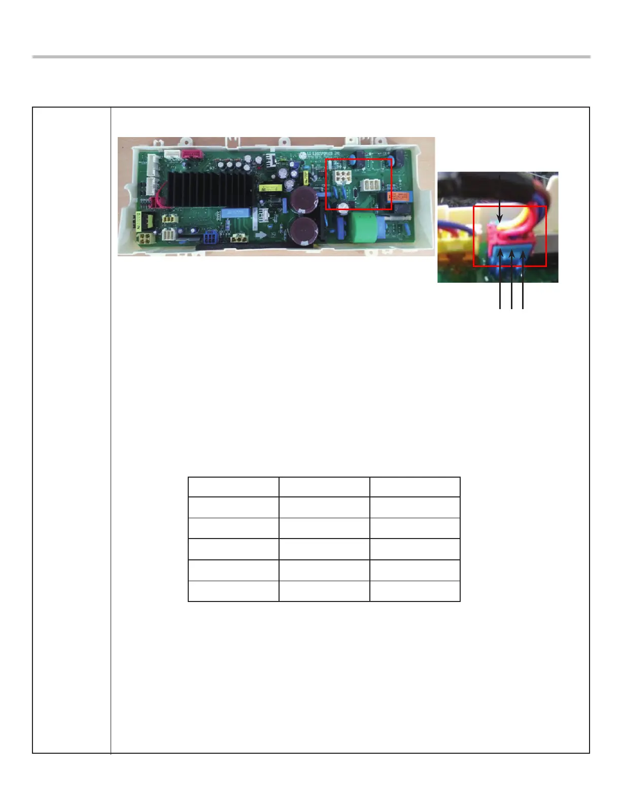
- Voltage Testing Hall Sensor from the Main PCB Assembly
1. Unplug power cord.
2. Remove rear panel.
3. Remove Washer Top.
4. Remove Main PCB Assembly cover as shown in Figure below.
5. Locate the Blue Hall Sensor 6 wire connector using wiring diagram wire colors as your guide.
6. Plug in power cord, close door, and press power button. DO NOT PRESS START!
7. Place meter leads on White & Gray wires. You should read 10 to 15 Vdc output from the Main
PCB Assembly to the Hall sensor. If no 10 to 15 Vdc is measured the control board is defective.
8. Place meters leads on Blue to Yellow. Turn motor rotor slowly by hand. You should measure a
pulsing 10 Vdc. Place meter leads on Red to Yellow. Turn motor rotor slowly by hand. You should
measure a pulsing 10 Vdc. If both tests measure a pulsing 10 Vdc, hall sensor and harness OK. If
either or both tests measures 9 to 10 volts, but does not pulse or change, Hall sensor has failed
and must be replaced. IF zero (0) voltage is measured on either test, check red & blue wires for
continuity. Repair or replace harness as needed.
Result
8-12 kΩ
8-12 kΩ
10-15 Vdc
10 Vdc
10 Vdc
Test Points
(1) to (2)
(1) to (3)
(1) to (6)
(2) to (6)
(3) to (6)
Remarks
Voltage Input
Pulsing Signal
Pulsing Signal
(1)(2)(3)
(6)
 Loading...