Service Manual of Rough Terrain Mobile Elevating Work Platform
59
wrench 1/2 16mm, torque wrench
QSP200, AT262 thread locker (on
demand)
Removing the rear axle assembly
△
! CAUTION: Risk of part damage.
The motor maintenance shall only be
performed by the dealers.
△
! CAUTION: Risk of part damage.
The working area and surface where this
step is performed must be clean, and no
impurities will enter the hydraulic system,
which may cause serious component damage.
It is recommended that the dealer perform
maintenance.
△
! CAUTION:
Before refitting, the O-ring of the removed
fitting and/or hose assembly must be replaced
and then tightened to the specified torque
Please refer to hydraulic hose and fitting
torque specifications.
1. Lock the steered wheel.
2. Mark, disconnect and plug the hydraulic hose
of driving motor.
△
! WARNING: Risk of personal injury.
Splashed hydraulic oil may penetrate and
burn the skin. Therefore, please loosen
hydraulic connectors very slowly to reduce the
oil pressure gradually. Do not spray or splash
oil.
3. Remove the fasteners of the driving motor.
4. Pull out the driving motor shaft from the
reducer, and remove the driving motor from
the machine.
△
! CAUTION:
An O-ring is installed between the driving
motor and the reducer. When installing the
driving motor to the machine, make sure that
the O-ring is in the correct position.
5. Lock the steered wheel and place the jack in
the middle of the steering end of the chassis.
6. Unscrew the wheel nuts, but do not remove
them.
7. Raise the machine by 5 cm. Place the bracket
under the chassis for the purpose of
supporting.
8. Unscrew the wheel nuts and remove the tires.
9. Place another jack under the reducer to
support and fix the reducer.
10. Remove the fasteners of the reducer and then
remove the reducer.
Outrigger assembly
Assembling the outrigger
cylinder
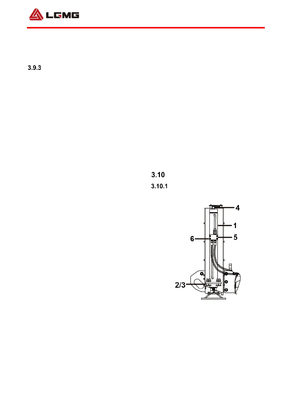
Fig. 3.51 outrigger cylinder
1. Outrigger cylinder 2. Outrigger cylinder
mounting bolt 3. Nut 4. Outrigger cylinder guide
stud 5. Outrigger solenoid valve ST5128-AB00 6.
Screw
1. Install part 1 to the mounting positions on both
sides of the support beam with parts 2 and 3,
and tighten it to the specified torque; apply
AT262 thread locker to bolts before installation;

 Loading...