EasyManua.ls Logo

Liebert ITA UPS 16kVA User Manual

Liebert ITA UPS 16kVA
48 pages
To Next Page IconTo Next Page
Page #1 background imageLoading...
Page #1 background image
Liebert ITA UPS 16kVA/20kVA
User Manual
Version
V1.0
Revision date January 26, 2010
BOM 31011782
Emerson Network Power provides customers with technical support. Users may contact the nearest
Emerson local sales office or service center.
Copyright © 2010 by Emerson Network Power Co., Ltd.
All rights reserved. The contents in this document are subject to change without notice.
Emerson Network Power Co., Ltd.
Address: No.1 Kefa Rd., Science & Industry Park, Nanshan District 518057, Shenzhen China
Homepage: www.emersonnetworkpower.com.cn
E-mail: support@emersonnetwork.com.cn

Table of Contents

Question and Answer IconNeed help?

Do you have a question about the Liebert ITA UPS 16kVA and is the answer not in the manual?

Liebert ITA UPS 16kVA Specifications

General IconGeneral
Power Rating16 kVA
Real Power16 kW
Frequency50/60 Hz
TopologyDouble Conversion Online
Form FactorTower
Relative Humidity0-95% non-condensing
Input Frequency50/60 Hz
Output Frequency50/60 Hz
Battery TypeValve-regulated lead acid (VRLA)
Typical Recharge Time4 hours
Operating Temperature0 to 40 °C
Storage Temperature-15 to 45 °C
Audible Noise55 dBA
Communication InterfaceRS-232, USB, SNMP
Protection FeaturesOverload, Short Circuit, Over Temperature
Input Voltage208/220/230/240 VAC (1-phase or 3-phase), 380/400/415 VAC (3-phase)
Output Voltage208/220/230/240 VAC (1-phase or 3-phase), 380/400/415 VAC (3-phase)
EfficiencyUp to 94%

Summary

Safety Precautions

Conformity and Standards

Lists compliance with EU directives and product standards for UPS.

High Leakage Current Warning

Essential earth connection and RCCB selection for leakage current.

Reflected Protection Warning

Use of zero-voltage contact closure signal for external circuit breaker.

Maintainable Components

Maintenance by trained personnel; safe operation.

Battery Voltage Hazard Warning

Chapter 1 Product Introduction

1.1 Features

Key features of the Liebert ITA UPS, including parallel connection and ECO mode.

1.2 Model Configuration

Describes available models (UHA3R-0160L, UHA3R-0200L) and their configurations.

1.3 Appearance And Components

1.3.1 Appearance

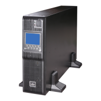
Shows the UPS appearance with front and rear panels.

1.3.2 Components

Details components on the front and rear panels of the UPS.

1.4 Operating Principle

1.5 UPS State And Operation Mode

1.5.1 Normal Mode

Describes UPS operation when mains input is normal.

1.5.2 Bypass Mode

Explains UPS behavior when switching to bypass mode.

1.5.3 Battery Mode

1.5.4 ECO Mode

1.5.5 Fault State

1.6 Specifications

Chapter 2 Installation

Professional Installation Warning

Emphasizes that installation must be done by qualified engineers.

Battery Hazards Warning

Details safety precautions when handling batteries due to high voltage.

2.1 Unpacking Inspection

Steps for unpacking the UPS and checking for damage.

2.2 Location

Guidelines for selecting an appropriate installation location for the UPS.

2.2.1 Distribution Room

2.2.2 Battery Room

2.2.3 Storage

Battery Storage Hazard

2.4 Mechanical Installation

2.4.1 Tower Installation

Step-by-step guide for installing the UPS in a tower configuration.

2.4.2 Rack Installation

2.5 External Protective Device

2.5.1 Rectifier And Bypass Inputting

Guidance on selecting protective devices for input circuits.

Earth Leakage Current

Requirements for RCD selection for UPS upstream distribution.

2.5.2 Battery Input

2.5.3 UPS Output

2.6 Connecting Power Cables

2.6.1 Cables Selection

Guidance on selecting appropriate cables based on current ratings.

2.6.2 Connecting I/O Cables

Distribution Mode and Terminal Block

Explains distribution modes and terminal block connections for I/O cables.

Single POD Options (Recommended)

3-in 1-out Common Source Configuration

3-in 1-out Split-Bypass Configuration

Self-Distribution

2.6.3 Connecting Battery Cables

2.7 Connecting Communication Cables

2.7.1 Dry Contact Communication Cable

Details on connecting dry contact communication cables and their pin descriptions.

2.7.2 USB Communication Cable

2.7.3 SNMP Card Communication Cable

2.8 Parallel System

2.8.1 Mechanical Installation

Steps for the mechanical installation of a parallel system.

2.8.2 Setting Parallel Addresses

How to set unique parallel addresses for UPS units using DIP switches.

2.8.3 Connecting Parallel Cables

Schematic for connecting parallel cables in a parallel system.

2.8.4 Connecting 1 + 1 Parallel POD Cables

Procedures for connecting cables between UPS and 1+1 parallel POD.

Connecting I/O Cables of 1 + 1 Parallel POD

2.9 Common Battery Strings

2.10 Double Bus System

2.10.1 System Installation

Overview of installing a double bus system for high reliability.

Chapter 3 Operation And Display Panel

3.1 Introduction

Overview of the UPS operation and display panel components.

3.1.1 LED Indicators

Description of the inverter and fault LED indicators.

3.1.2 Audible Alarm (Buzzer)

Describes the types of audible alarms and their meanings.

3.1.3 Control Buttons

3.1.4 LCD And Menu Buttons

3.2 LCD Screen Types

3.2.1 Start Screen

Describes the initial start screen during UPS self-test.

3.2.2 Primary Screen

3.2.3 Default Screen

3.3 Detailed Description Of Menu Items

Function Settings

Keypad Window

3.4 Prompt Window

3.5 UPS Alarm Message List

Alarm Messages (Rectifier, Bypass, Inverter)

Alarm Messages (DC Bus, Communication)

Chapter 4 UPS Operation Instructions

4.1 UPS Start-up

Covers normal and battery module start-up procedures.

4.2 Transferring Procedures Between Operation Modes

Normal to Battery Mode Transfer

How the UPS switches to Battery mode during mains failure.

Normal to Bypass Mode Transfer

Procedure to switch the UPS from Normal mode to Bypass mode.

Bypass to Normal Mode Transfer

Procedure to switch the UPS from Bypass mode back to Normal mode.

Normal to Maintenance Bypass Mode

Steps to switch the UPS to maintenance bypass for servicing.

4.3 Complete Shutdown Procedure

4.4 EPO Procedure

4.5 Auto Restart

4.6 UPS Reset Procedure

4.7 Language Selection

4.8 Changing Current Date And Time

4.9 Control Password

Chapter 5 Maintenance

5.1 Fan Maintenance

Guidance on checking and maintaining UPS fans.

5.2 Battery Maintenance

Recommendations for maintaining the internal battery module.

5.3 Cleaning UPS

Instructions for cleaning the UPS, especially ventilation holes.

5.4 Checking UPS State

Recommended procedures for checking the UPS operational status.

5.5 Checking UPS Functions

Note that checking UPS functions may cause power interruption.

Checking UPS Functions Procedures

Appendix 1 Battery Module

Appearance

Shows the appearance of the battery module.

Rear Panel Components

Details the components on the rear panel of the battery module.

Replacing Battery Fuse

Appendix 2 Optional Part List

Optional Part List

Lists optional parts for the UPS system.

Related product manuals