16
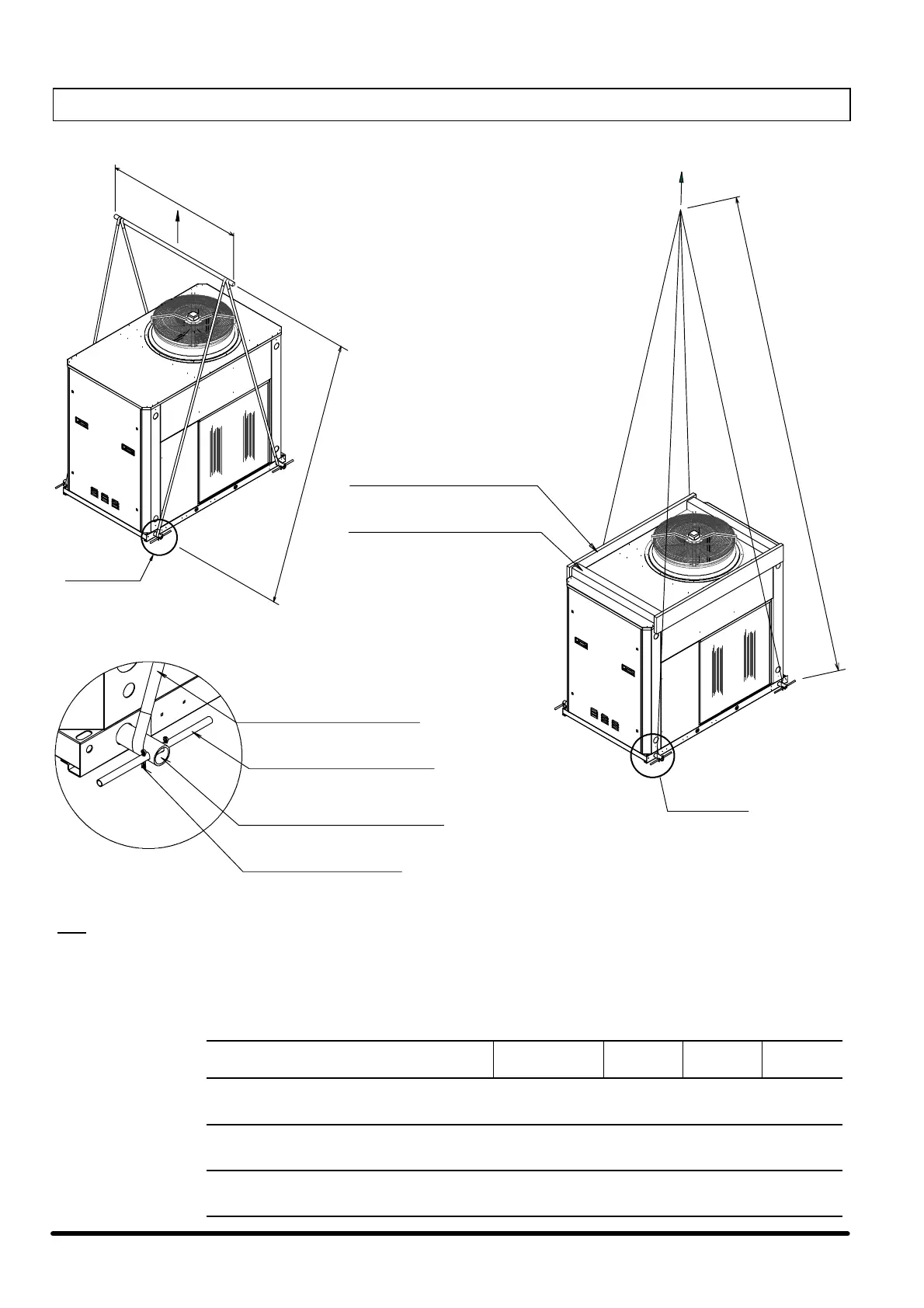
Fig. 2 --- Lifting instructions with tubes
LIFTING TUBE
(NOT SUPPLIED)
(BASE HOLES Ø45)
”A”
”B”
”C”
LIFTING SYSTEM WITH TUBES
BELT OR CHORD
BLOCKING PEG
(NOT SUPPLIED)
SPLIT PIN
(NOT SUPPLIED)
PROTECTION PLANK
RIGID STRUTS
(POSSIBILY STEEL)
PART. “A”
PART. “A”
PART. “A”
N.B: Place the lifting tubes in the holes in the base indicated by the words “LIFT HERE”. Lock the ends of the tubes in position with
the locking pins and split pins as shown above “A”.
The capac ity of the lifting gear must be adequate to lift the load in question. Check the weight of the unit, the capacity of the
lifting gear and ropes and the condition and suitability of the aforementioned equipment. Lift the unit with a speed suitable
for the load to be moved, so as not to damage the structure.
Lifting
Models Fans number
“A”
(m)
“B”
(m)
“C”
(m)
CBH / SBH 004---006---007---204---206---207
CLH / SLH 004---006---204---206
CQH / SQH 004---204
1 1.7 ' 3 ' 8
CBH / SBH 008---011---014
CLH / SLH 007---207---008---011
CQH / SQH 006---007---206---207---008
2 1.7 ' 4 ' 8
CBH/SBH016
CLH / SLH 014---016
CQH / SQH 011---014---016
3 1.7 ' 4 ' 8
 Loading...