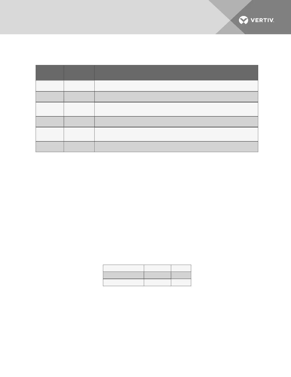
EC-fan Fault Conditions
Fault
Condition
Reset Trigger Description
Phase Failure Automatic
One phase is missing. In this case the motor will come to a stop and then automatically restart when all phases
are present.
Locked/Blocked
Rotor
Automatic The rotor is blocked. Once the locking mechanism has been removed, the motor will automatically restart.
Hall Effect
Sensor Error
Manual
(Mains/Software)
The Hall Effect Sensor is used to monitor fan speed. If there is a hall sensor communication failure with the
electronics, the motor will stop. In this case there has to be a manual restart (either with the mains power or
software).
Motor Over
Temperature
Manual
(Mains/Software)
The motor will stop in the event there is a motor over temperature condition. In this case there has to be a
manual restart (either with the mains power or software).
Electronics
Over
Temperature
Manual
(Mains/Software)
The motor will stop in the event there is an electronics over temperature condition. In this case there has to be
a manual restart (either with the mains power or software).
Line
Under-Voltage
Automatic Once the line voltage returns within permitted operating range, the fan will automatically restart.
Table 9.2 EC-fan Fault Conditions
EC-fan High-voltage Tests
1. Check Fuses. If fuses are okay, perform the following:
• Check all connections.
• Make sure connections are on the wire strand and not on the wire insulation.
• Cycle Power. Disconnect mains voltage to power down the motor and then re-apply
power.
• Check mains voltage at each phase (phase to ground) at the KL1 connector.
Confirm phase failure not present.
• Check that the voltage is within the acceptable voltage range at the KL1
connector. Confirm line under-voltage is not present.
2. Check Fuses. If fuses are blown, perform the following:
• Check resistances across the phases at the KL1 connector and note them in the
following table..
NOTE: Power wires must be removed from the motor for resistance test.
L1 - L2 Ohm
L2 - L3 Ohm
L1 - L3 Ohm
• Resistances should be similar for all 3 readings.
Vertiv | Liebert® PDX™ and PCW™ Installer/User Guide | 65