Do you have a question about the Liebert AC4 and is the answer not in the manual?
Explains accessing unit via LCD and Service Terminal Interface for configuration and monitoring.
Describes alarm and event logs viewable on LCD or Service Terminal.
Lists discrete input alarms, loss of power, no standby, etc.
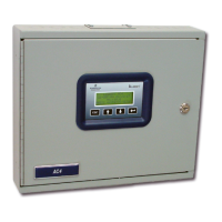
Details the enclosure's depth, display, lock, material, and mounting.
Shows external devices connected to inputs/outputs and remote access.
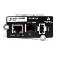
Describes connectors, LEDs, ports, and power for the controller board.
Explains LEDs indicating status of inputs, outputs, and common alarm.
Explains how the AC4 functions after a device state change or alarm.
Discusses indoor mounting, access, electrical service, and wall support.
Instructions for inspecting the carton and components for damage.
Steps for physically mounting the unit onto a wall surface.
Detailed steps for marking, drilling, and securing the panel to the wall.
Instructions for mounting the unit recessed within a wall.
Steps for cutting a wall opening and securing the panel for flush mounting.
Details the 24VAC power requirement and recommended power units.
Table detailing wire types, lengths, and ratings for various connections.
Step-by-step guide for wiring digital inputs to the terminal block.
Step-by-step guide for wiring digital outputs to the terminal block.
Explains setting output jumpers for fail-safe operation.
Details connecting auxiliary notification devices to the common alarm relay.
Describes the RS232 port for Service Terminal Interface connection.
Describes the initial screen displayed at startup.
Explains the structure and access to functions via the Main Menu.
Instructions for viewing currently active alarms, logs, and device statuses.
Instructions for viewing currently active alarms, up to a maximum of 40.
Instructions for accessing the alarm log, which stores up to 99 alarm records.
Explains backing up the alarm log via the Service Terminal Interface.
Instructions for viewing the event log, which tracks changes in input/output status.
Explains backing up the event log via the Service Terminal Interface.
Instructions for viewing the current status of the four digital inputs.
Instructions for viewing the current status of the four digital outputs.
Explains silencing audible alarms and resetting common relay via Service Terminal.
Explains backing up alarm and event logs to a remote computer.
Instructions for entering a password to access system and control functions.
Lists options for configuring inputs, outputs, common alarm, and system details.
Guides on configuring individual digital inputs.
Instructions for renaming digital inputs, which also affects output names.
Explains setting inputs as Normally Open (NO) or Normally Closed (NC).
Explains configuring inputs as Alarmable (AL) or Event (EV).
Instructions for setting alarmable inputs to Latched (Y) or Unlatched (N).
Explains setting a time delay for input responses to alarms or events.
Configures how the common alarm relay behaves with silence.
Guides on defining zones and assigning outputs to them.
Guides on configuring digital outputs.
Explains setting outputs as Normally Open (NO) or Normally Closed (NC).
Sets output mode to Operating (OP), Standby (ST), or Not Used (NU).
Configures whether outputs are enabled or disabled when a device is in alarm.
Explains configuring output jumpers for fail-safe behavior during power loss.
Accesses options for password, date/time, site ID, backup, and defaults.
Instructions for changing the system access password.
Sets the system date, time, and daylight saving adjustment.
Assigns a name to identify the Liebert AC4's location for alarms.
Allows backing up and uploading configuration settings via the Service Terminal.
Restores all system settings to their original factory values.
Updates the Liebert AC4's firmware to the latest version.
Configures device rotation, standby testing, delay times, and response to alarms.
Sets up scheduled rotation of devices between operating and standby modes.
Determines device behavior when a standby device fails upon activation.
Sets a delay timer to ignore inputs after an output changes state.
Sets a delay timer before changing an output's state.
Allows manual control of digital outputs, overriding automatic settings.
Provides options to clear active alarms and delete log records.
Clears all active alarms, including resetting Latched alarms.
Lists technical specifications like dimensions, power, processor, and I/O.
Compares functions available via LCD and Service Terminal Interface.
Steps to create a new connection in HyperTerminal.
Instructions to initiate communication via HyperTerminal.
Explains Main Menu options for viewing status and system control.
| Brand | Liebert |
|---|---|
| Model | AC4 |
| Category | Control Unit |
| Language | English |