1.5 Typical Configuration
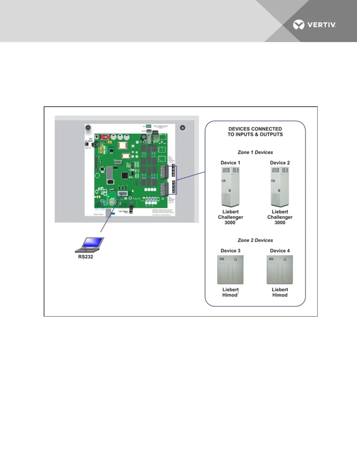
Figure 1.3 below shows an example of external devices connected to the Liebert AC4 controller board.
There may be up to four devices connected to the four digital inputs and four digital outputs. Remote
access is available through the Service Terminal Interface.
Figure 1.3 Typical Configuration
1.6 Controller Board Overview
The Liebert AC4 controller board has connectors for four digital inputs and four digital outputs, as shown
below. The board comes complete with light emitting diodes (LEDs) to display the status of connected
devices, a serial communications port, a power connection and other features necessary to control your
operation.
Vertiv | Liebert® AC4 User Manual | 9