3.2 Connecting Digital Inputs and Outputs
The digital inputs and outputs are on the lower right side of the Liebert AC4 printed wiring assembly
board. This section describes how to connect devices to the Liebert AC4’s inputs and outputs.
Each input is tied to an output with the same number:
• Input 1 is tied to Output 1 (default name: Device_1)
• Input 2 is tied to Output 2 (default name: Device_2)
• Input 3 is tied to Output 3 (default name: Device_3)
• Input 4 is tied to Output 4 (default name: Device_4)
Up to four devices may be connected to the Liebert AC4. Each device must be connected to an input and
an output with the same number.
To determine the proper wire size, see Wiring and Connections on the previous page.
NOTE: Each terminal block is a removable assembly to permit easier connection of more than one input
or output at a time. If making multiple connections, grasp the upper portion of a block and pull firmly
until the assembly pulls apart.
NOTE: After making the connections, push the removed piece back into the portion attached to the
printed wiring assembly until the terminal block pieces lock together.
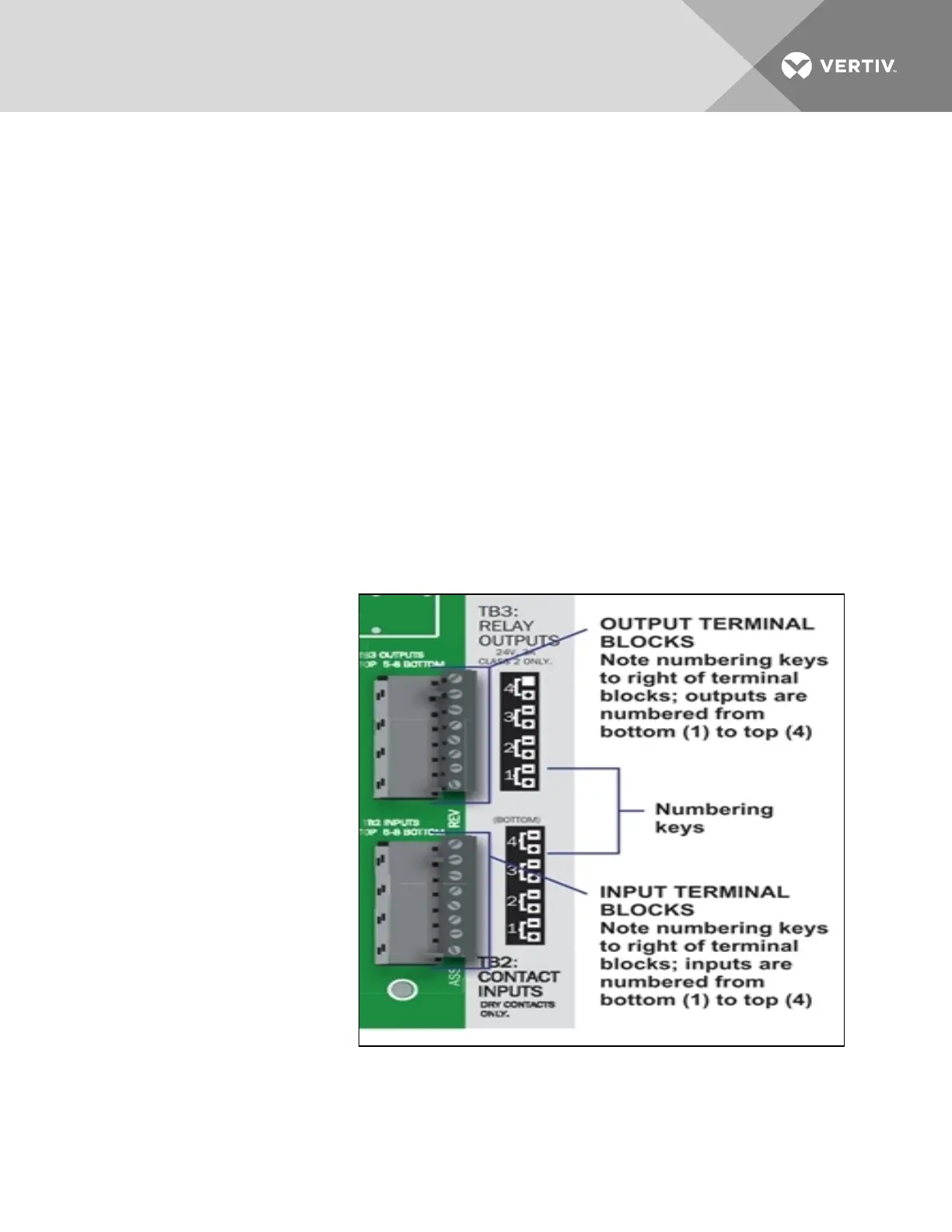
3.2.1 Connecting Digital Inputs
The four digital inputs are on the
lower right side of the Liebert AC4,
just below the output terminal
blocks, as shown at right. These
inputs are numbered 1 through 4.
To connect an input:
1. Turn Off electrical
power to the Liebert
AC4.
2. If necessary, remove a
conduit knockout to
permit wire entry into
the Liebert AC4
enclosure.
3. Bring the wire(s) into
the Liebert AC4
enclosure through a
conduit knockout or
access slot.
4. Loosen the appropriate
screw and slip the
stripped end of the wire
into the terminal block.
5. Tighten the screw until it holds the wire snugly.
Vertiv | Liebert® AC4 User Manual | 22