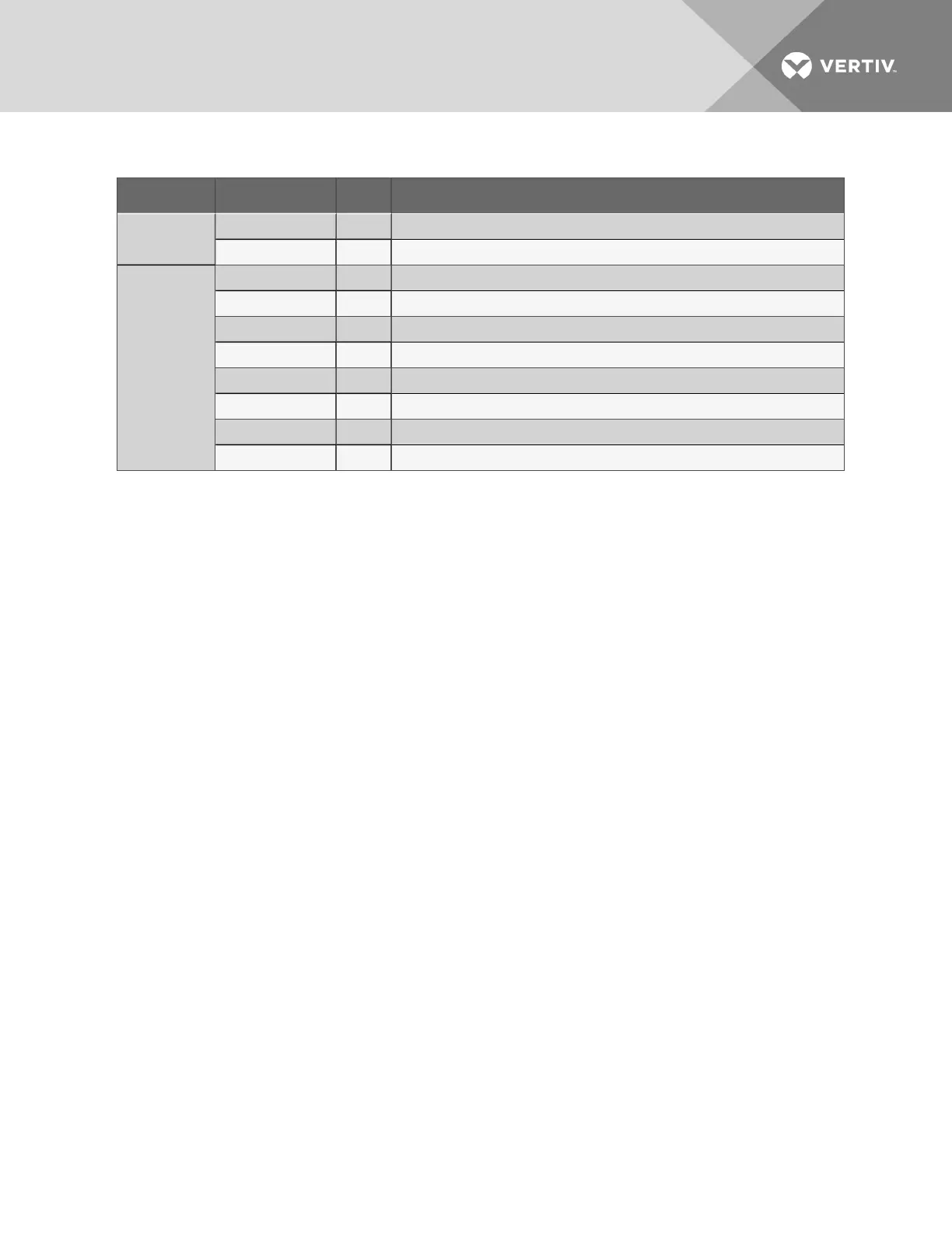
LED Type LED Color Description
485 RX Green Not used
485 TX Green Not used
Input LEDs
INPUT1 Red Not used
INPUT2 Red Not used
INPUT3 Red Not used
INPUT4 Red Not used
INPUT5 Red Indicates input 1 is ON or energized
INPUT6 Red Indicates input 2 is ON or energized
INPUT7 Red Indicates input 3 is ON or energized
INPUT8 Red Indicates input 4 is ON or energized
Table 1.2 LED indicators summary (continued)
1.8 Typical Sequence
Figure 1.4 on the next page shows a typical sequence of how the Liebert AC4 functions after detecting a
change in a monitored device. Many responses depend on configuration settings. This example shows
what happens when a digital input changes state—assuming the input is defined as alarmable—and
when the condition returns to normal.
Vertiv | Liebert® AC4 User Manual | 13