If Zone 1 has: Zone 2 must have:
4 or 3 outputs 0 (not used)
2 outputs 0 (not used) or 2 outputs
0 (not used) 2 or 3 or 4 outputs
Table 7.5
Possible combinations - outputs per zone
7.6 Setup System - Setup Outputs
The Liebert AC4 has four outputs that may be configured individually. These outputs correspond to the
four numbered inputs. For example, Device_1 is the unit connected to Input 1 and to Output 1.
The output name is the same as the input name, as described in Change Label (Name of Input) on
page45.
To configure an output:
Log In and Choose Setup System
• From the Main Menu, use the arrows to choose System and
Control, then press Enter (see Login on page41 for help).
• Enter your password at the Login screen.
• From the System and Control Menu, use the arrows to choose
Setup System, then press Enter.
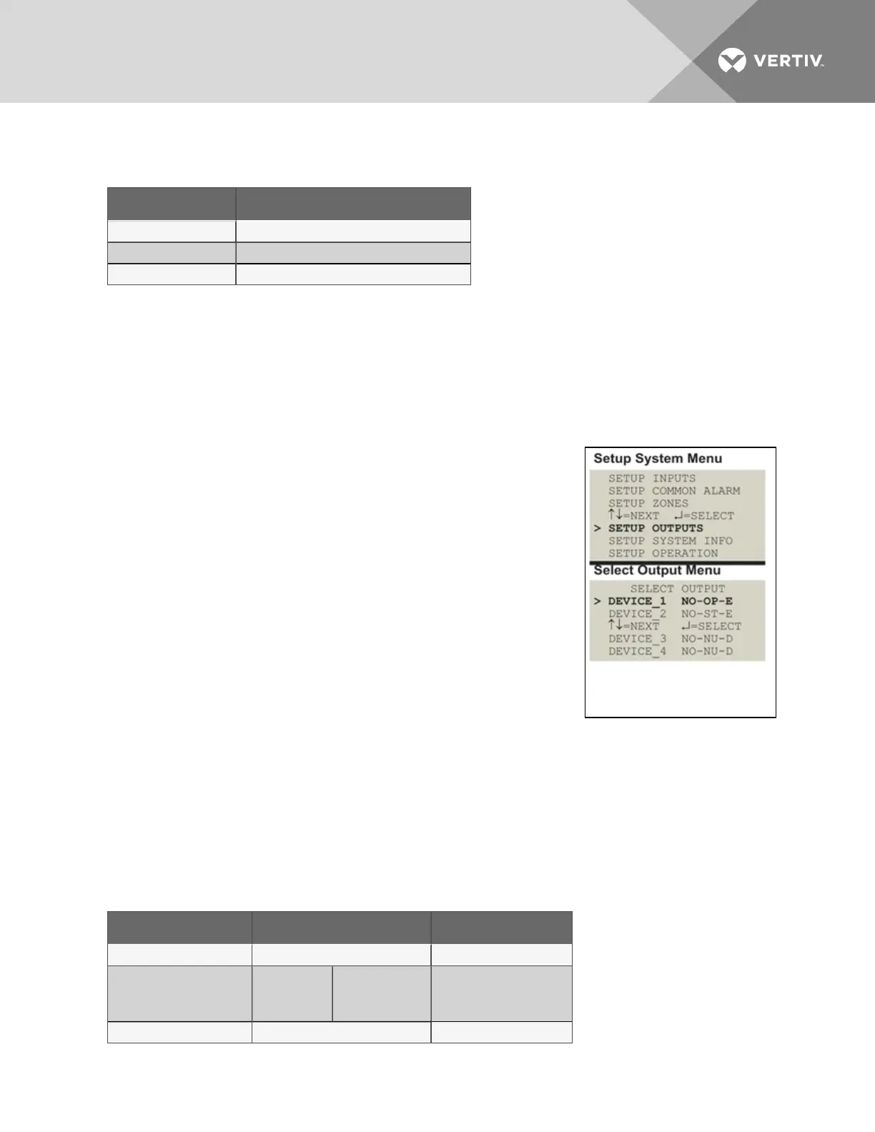
Select an Output to Configure
• From the Setup System Menu, shown at right, use the arrows to
choose Setup Outputs and press Enter.
• From the Select Output Menu, choose an output—for example,
Device_1—and press Enter.
Table 7.6 below shows digital output features and their default settings: you may define an output as
normally open or normally closed, set the device’s mode—operating, standby or not used—and specify
whether to disable the device when an alarm occurs.
Use the steps following Table 7.6 below to change the default settings for any digital output.
Feature Default Other Options
NORM OPEN/CLOSE NO (Normally open) NC (Normally closed)
MODE
Outputs1-3:
Output4:
OP (Operating)
ST (Standby)
OP (Operating)
ST(Standby)
NU (Not Used)
IN ALARM E (Enable) D (Disable)
Table 7.6
Default settings - digital outputs
Vertiv | Liebert® AC4 User Manual | 50