Chapter 3 Electrical Assembly
25
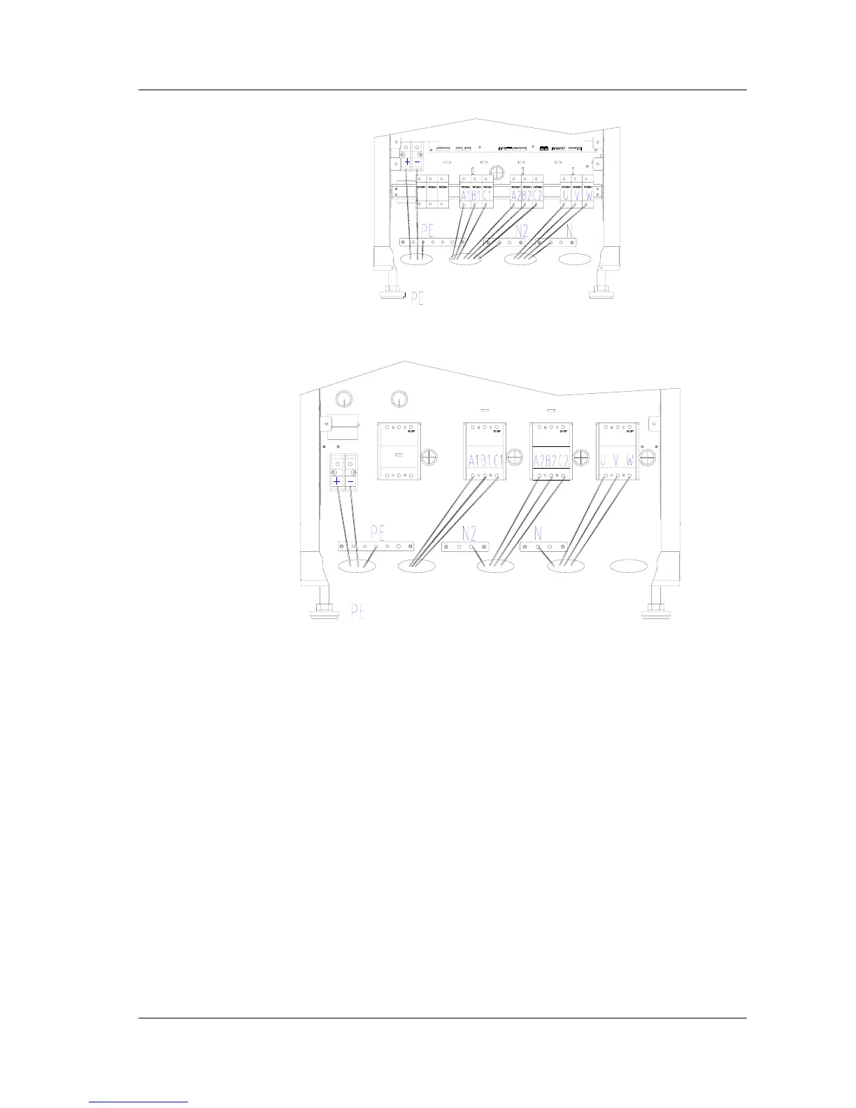
Battery
cables
UPS input
input N
UPS output
output N
Fig. 3-1 20/30kVA UPS bottom cable output
Battery cables
Rectifier input
Bypass input
Bypass N
UPS output
Output N
Fig. 3-2 40/60kVA UPS cable connection at bottom
2. Cable routing
1. Bottom entry configuration – the cables are input and output from the bottom of
the UPS
2. Top entry configuration – the cables are input and output from the top of the
UPS. To do this, punch out the cable entry cut-outs on the top of the UPS,
and feed the cables through the cutouts and guide them through the metal
conduit to the bottom of the UPS. From the front view, the battery cable, the
input power cables of rectifier and bypass input cables should be input from
the left. The output cable and signal cables should be input from the right.
The layout of the cables is shown in Figure 2-8.