Chapter 5 Operation of Display Panel
43
Chapter 5 Operation of Display Panel
5.1 Display panel
5.1.1 Layout of Display Panel
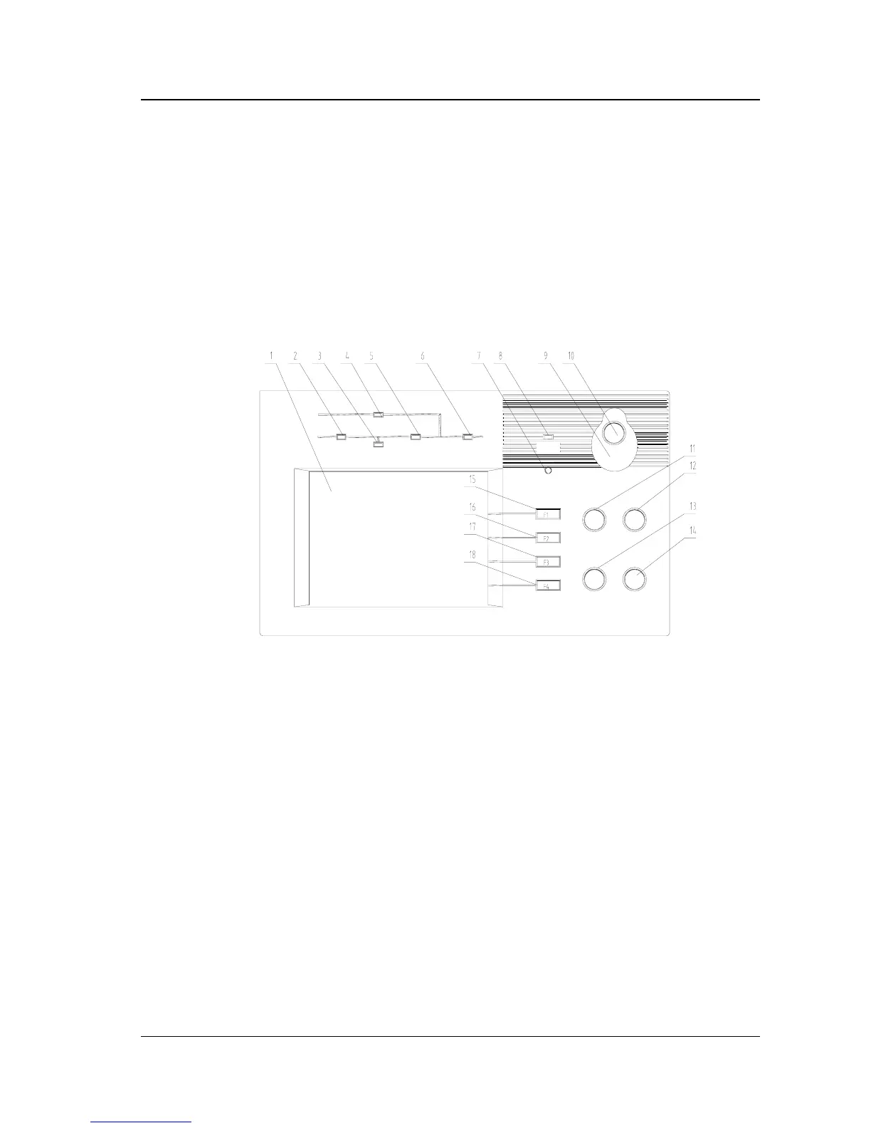
The display panel of the UPS is shown in Figure 5-1.
Start
Shutdown
Faullt clear
Mute
1:LCD 2:Rectifier indicator
3:Battery operation indicator 4:Bypass source indicator
5:Inverter operation indicator 6:UPS output indicator
7:Buzzer 8:Alarm indicator
9: cover used for preventing wrong operation of Emergency shutdown button
10:Emergency shutdown button (EPO) 11:Inverter start button
12:Inverter shutdown button 13:Fault clear button
14:Alarm mute button 15:F1 Functional key
16:F2 Functional key 17:F3 Functional key 18:F4 Functional key
Fig. 5-1 Display Panel
The display panel is divided into three sections:
1.LED section
2.Functional Keys
3.LCD