Chapter 3 Electrical Assembly
31
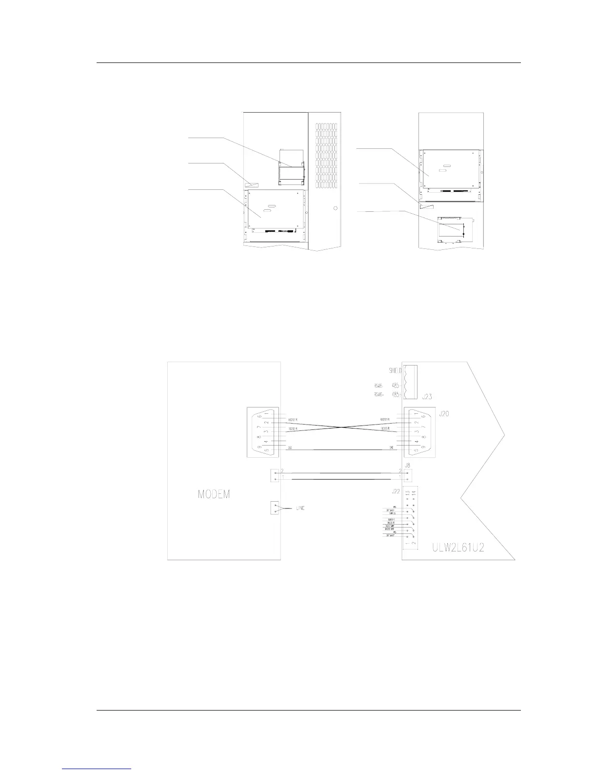
2) Connection of modem
MODEM or SNMP
SNMP cables
Monitoring board
Monitoring board
SNMP cables
MODEM or SNMP
20/30kVA Front view when
Front door is opened
40/60kVA Front view when
right door is opened
Fig. 3-10 Installation of MODEM or SNMP
1. Figure 3-10 shows the location of Modem and SNMP card. Before installing the
modem, the user should remove the iron box use for SNMP card and installed the
modem there.
Communication port
Power source
serial pore
communication port
communication port
Fig. 3-11 MODEM Connection Method
2.Connecting the communication cables. The communication cables of modem are
connected to J20.
3. Connection of power source cables. Connect the power source cables of modem
directly to J8. The Pin 1 of J8 is ground. Pin 2 is 12V power.
4.Connection of Telephone line. Connect the telephone line after connecting the
power source and communication cables to realize remote communication.