PFCL Elite 6 / PFCL Elite 12
- 9 -
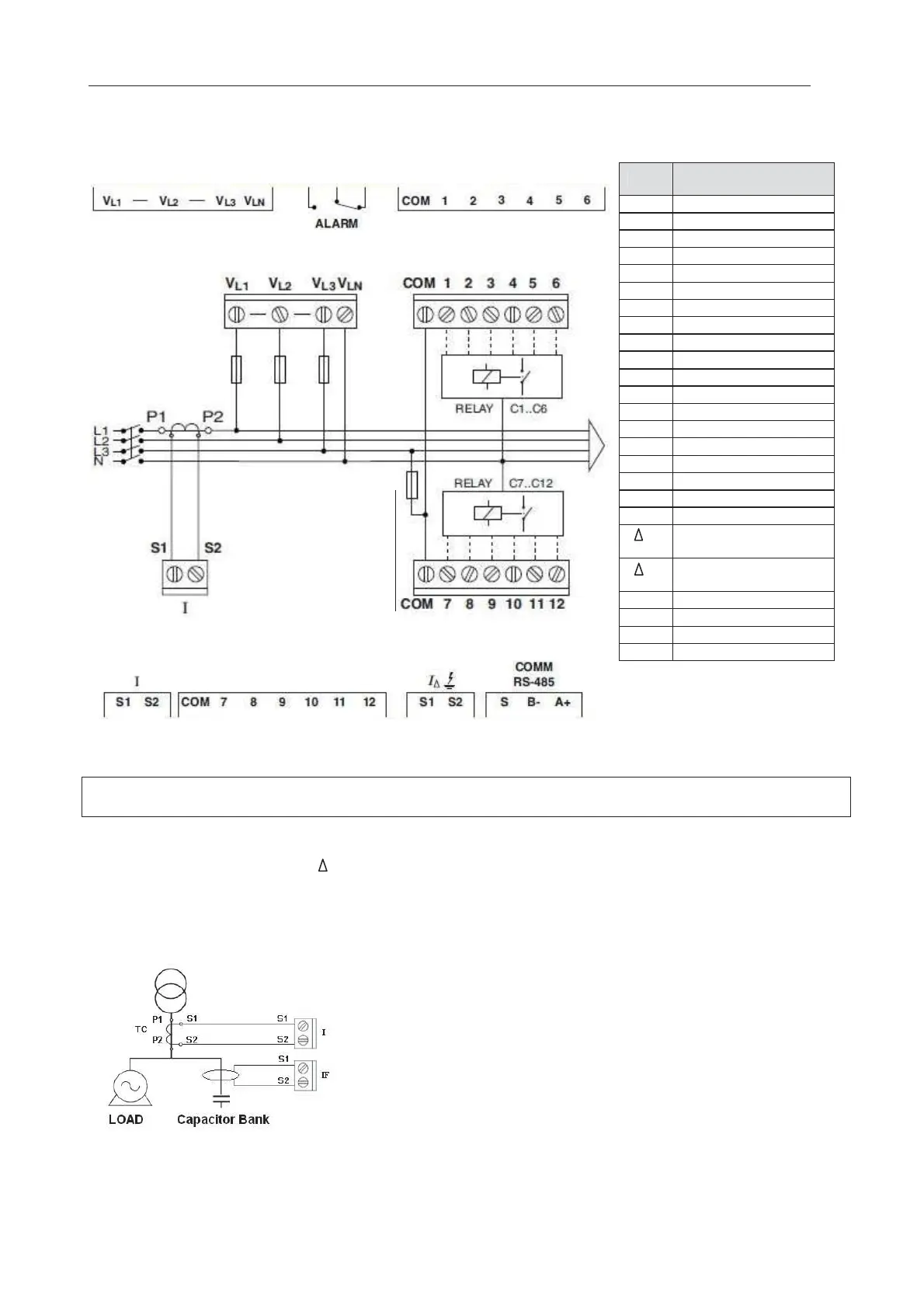
2.2.4 Connection diagrams. PFCL Elite 6/12.
Fig. 2.2.- PFCL Elite 6/ PFCL Elite12 Connection diagram
(*) Nominal voltage, depending
on the type. See label on the
unit.
No.
Description of the
erminals
U
L1
Voltage input L1 (*)
U
L
Voltage input L2 (*)
U
L
Voltage input L3 (*)
U
Voltage input LN (*)
COM Relay common
1 Relay output 1
2 Relay output 2
3 Relay output 3
4 Relay output 4
5 Relay output 5
6 Relay output 6
7 Relay output 7
8 Relay output 8
9 Relay output 9
10 Relay output 10
11 Relay output 11
12 Relay output 12
I S1
Current input S1
I S2
Current input S2
I S1
Leakage current input
S1
I S2
Leakage current input
S2
A+ RS-485 Input A(+)
B- RS-485 Input B(-)
S RS-485 S Input
ALARM
NC or NO Relay output
NOTE: The two COM terminals are not internally connected. In the case of the model with 12 relay outputs,
the two COM outputs of the regulator must be short-circuited.
Leakage current connection ( I )
The leakage current transformer must be connected in such a way that it measures the current of the
capacitor bank. This will detect any leakage in the capacitors of the capacitor bank.
The transformer must have a ratio with 500 spirals and the current measured must not exceed 1 A AC.
Fig. 2.4.- Connecting the leakage current transformer (I¨)
Only for
PFCL Elite 12

 Loading...
