Vibration Therapy Collection 9 8 TrimLite User Manual Lifepro
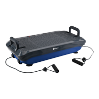
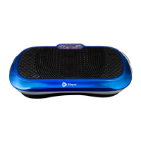
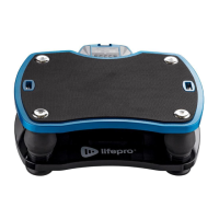
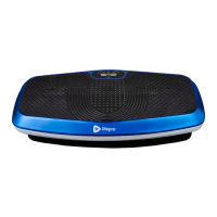
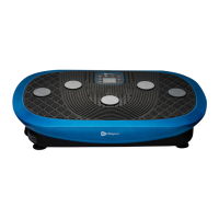
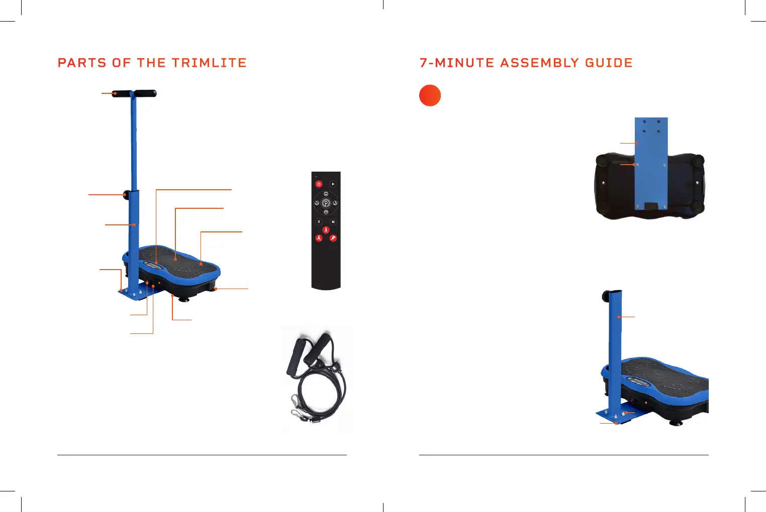
PARTS OF THE TRIMLITE
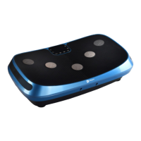
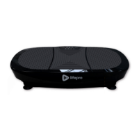
TrimLite Vibration
Plate
Resistance
Bands (2)
Remote
Control
Upper Post
& Handlebars
Lower Post
Height
Adjustment Knob
Power
Switch
Power
Cord Jack
Baseplate
Metal Resistance
Band Bars* (2)
Control Panel
Non-slip Rubber
Surface
Accupoints
(Magnetic Therapy
Stones)
Suction Cup
Feet (4)
* Located on the underside of the machine. During assembly you will
rotate the bars outward and attach the two included resistance bands.
ASSEMBLY NOTES
• Assemble the TrimLite on a flat, sturdy floor.
• Ensure the space is free of obstructions.
7-MINUTE ASSEMBLY GUIDE
ATTACH THE BASEPLATE
AND LOWER POST
1. Gather the baseplate (A), lower
post (B), eight screws (D), four cap
nuts (E), wrench (G), and hex key (H).
2. Tilt the TrimLite up onto its back edge,
so the bottom faces you and power
switch and power cord jack face up.
3. Align the four wide-set screw holes in
the baseplate with the four holes on
the underside of the vibration plate.
See Figure 1.
4. Use the hex key to insert four screws
to secure the baseplate to the
underside of the machine.
5. Position the base of the lower post on
the TOP side of the baseplate.
6. Align the screw holes in the lower post
with the holes in the baseplate.
7. Insert the four remaining screws
through the BOTTOM of the baseplate
and through the screw holes in the
base of the post. See Figure 2.
8. Screw a cap nut onto the end of each
screw.
9. Use the hex key and wrench to fully
tighten all four cap nuts.
10. Return the TrimLite to its upright
position.
1
Figure 1
A
D
Figure 2
B
A
E