M8 / M8P Installation Manual
2 3
Table of Contents
Description .....................................1
Specifications ...................................1
Regulatory Information ............................1
Mounting the Power Control Module .................1
Power Control Module Overview. ....................2
Connecting the Power Control Module ................4
Input and Output Wiring ...........................5
Programming ...................................6
Application Example .............................10
Description
The M8/M8P power control modules add 8 zones to an FPO
power supply system for powering and monitoring locks,
cameras, or other critical devices. The M8/M8P MUST be used
with an NL4 network module. The M8/M8P accepts either one
or two voltage sources, either of which are selectable for out-
put on a zone-by-zone basis. Each input is fully programmable
via software to accept a voltage, dry contact, or open collector
input. Each zone output is selectable via software for FAI op-
eration, constant output, maglock output, or fail-safe or fail-se-
cure doorstrike outputs. Output zone 8 is also programmable
as a dry contact output. The suffix "P" added to the model
number denotes Class 2 Power Limited outputs.
Specifications
Power Input
Voltage 12 or 24VDC nominal
Current 12A maximum
Standby Current 300mA
All lock control relays active
Zone Input
Voltage Input 12 or 24VDC
Max Current 10mA
Zone Output
Voltage Same as input
M8 Current
3.0A resistive
M8P Current
2.5A resistive (Class 2 Power Ltd)
Fuse
3A ATM automotive style (M8 only)
Size M8/M8P
6.00" x 4.00" x 1.4"
(152mm x 64mm x 36 mm)
Weight M8/M8P 0.35lb (0.16kg)
Regulatory Information
The equipment discussed within this manual has been tested
to the following standards:
• UL294, UL603, UL1076
• ULC S318, ULC S319
• CSA C22.2 #205
• CSFM Approved
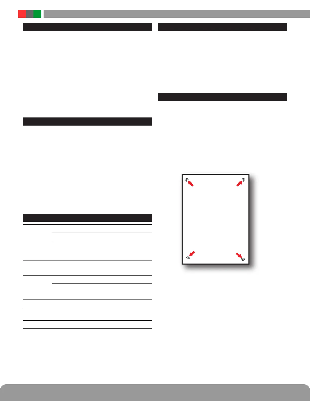
Mounting the Power Control Module
Mounting of the board to an enclosure is via the four
snap-in standoffs supplied.
1. Locate the appropriate mounting holes in the enclosure
and snap the standoffs into the holes.
2. Align the board mounting holes with the standoffs (be
sure the PC board is properly oriented) and snap the
board onto the standoffs.
3. Connections to the module shall be completed within
the same room, not exceeding a length of 3 m.
Class 2 power limited wiring must be seperated from non-power limited wiring by
a minimum of 1/4 inch and must use seperate knockouts.
• The installation and all wiring methods shall be in accordance with ANSI/
NFPA70 and all local codes.
For ULC compliance, installation and all wiring methods shall be in accordance
with the Canadian Electrical Code, C22.1, Part I, Section 32 .
All input wiring to the module shall be located within the same room (3 m).
 Loading...
