4
H
G
Table Stand
Power Cord
Your Console has been preprogrammed with your system. No additional steps are necessary.
2
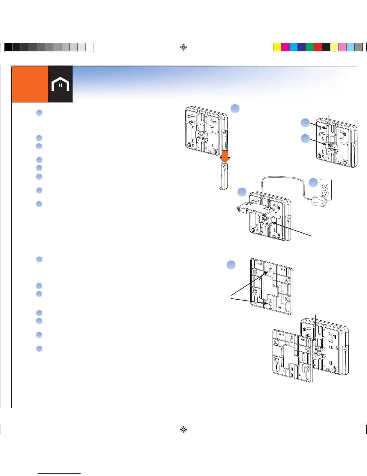
Connect Console
E
F
B
Console Back View
Battery Compartment
A
Put the Console near a frequently used door, ideally in a
different room than the Base/Cellular Gateway
*BUT NO MORE THAN 100 FEET FROM THE
BASE/CELLULAR GATEWAY
Remove the battery compartment door
Plug the battery pack into the plug receptacle and insert
the battery into the battery compartment
Snap on the battery compartment door
Connect power adapter to the back of the Console
Route the power adapter cord through the channel
toward the top of the Console
Snap the table stand provided in the kit onto
the back of the Console
Plug the power adapter into nearby electrical
wall outlet that is not controlled by a switch
B
C
D
E
F
G
H
Wall Mounting
A
Select a wall location and use the mounting plate as a
template for marking the wall for placement.
NOTE: TO MOUNT THE CONSOLE ONTO AN EXISTING
TELEPHONE WALL PLATE (NOT INCLUDED) BEGIN AT STEP D).
Drill 3/16” holes and insert drywall anchors (provided) into the holes.
Screw the mounting screws into the anchors leaving the screws heads
exposed approximately 3/8” (may require adjustment to achieve a
tight fit)
Connect power adapter to the Console.
Route the power adapter cord through the channel of the wall
mounting plate.
Slide the Console with mounting plate onto the wall screws
or phone mounting plate.
Plug the power adapter into nearby electrical wall outlet that is not
controlled by a switch.
B
C
D
E
F
G
To mount the Console to a wall, complete the following steps:
Mark Spot
On The Wall
Optional: Connect to
the telephone line here
(not included)
A