
J
Jessica BrownAug 20, 2025
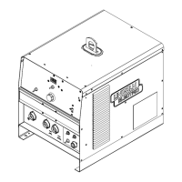
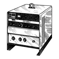
Why is the welding arc variable or sluggish on my Lincoln Electric IDEALARC CV-400-I Welding System?
- DDana LyonsAug 20, 2025
A variable or sluggish welding arc on your Lincoln Electric Welding System could be due to: 1. A poor work or electrode connection. Check and clean all connections. 2. Welding leads that are too small. Check the table in this manual for the correct size. 3. Welding current or voltage that is too low. Check the procedures for recommended settings. 4. A defective SCR bridge. Check and replace it if it is defective.