Do you have a question about the Lincoln Electric Idealarc DC600 9773MSP and is the answer not in the manual?
Explains risks and precautions related to electric shock when operating welding equipment.
Details risks from arc rays and necessary protective measures for eyes and skin.
Covers dangers of welding fumes and gases, emphasizing ventilation and respiratory protection.
Warns about fire and explosion risks from sparks and hot materials, requiring fire prevention.
Outlines safety measures for handling compressed gas cylinders to prevent explosions.
Covers safety related to electrical input and grounding for powered equipment.
Details safety guidelines specific to operating and maintaining equipment with engines.
Addresses potential hazards from EMF fields and precautions for pacemaker wearers.
Provides detailed technical data, ratings, and dimensions for the IDEALARC DC-600.
Outlines essential safety measures to be followed before and during the installation process.
Details recommended placement for air circulation and instructions for safely stacking multiple units.
Emphasizes the need for a stable, level surface to prevent the machine from toppling.
Explains how to connect electrical input power to the machine, matching voltage and frequency.
Details the importance of grounding the machine frame to a good electrical earth ground.
Guides on connecting three-phase AC power leads to the input contactor terminals.
Guides users through changing machine voltage settings via the reconnect panel for different power sources.
Details how to connect electrode and work leads to the output terminals and secure strain relief loops.
Provides instructions for connecting semi-automatic or automatic wire feeder control cables to the machine.
Explains how to connect for stick welding or air carbon arc cutting operations.
Highlights critical safety warnings specific to operating the welding equipment.
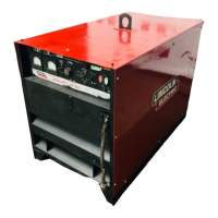
Introduces the IDEALARC DC-600, its SCR control, and supported welding processes.
Lists recommended welding or cutting processes and compatible equipment for the machine.
Describes the standard controls and features available on the machine's front panel.
Highlights key design features that contribute to the machine's performance and usability.
Details the machine's welding capacity and duty cycle ratings, including thermal protection.
Describes the function and location of all operator controls and adjustments on the front panel.
Provides a step-by-step guide for starting and operating the machine in local control mode.
Explains how to control the machine's output from a remote location using specific accessories.
Offers guidance on selecting welding modes and settings for different processes and applications.
Details setup and operation for specific wire feeders like NA-3, NA-5, LN-8, LN-7, and LN-9.
Lists available optional accessories and their functions for enhancing machine capabilities.
Explains how to install and connect the Multi-Process Switch for versatile welding operations.
Details connecting various wire feeders (NA-3, NA-5, LN-8, LN-9, LN-7) to the IDEALARC DC-600.
Describes optional accessories like undercarriages for mobility and meters for monitoring.
Stresses safety measures, particularly electric shock hazards, before performing maintenance.
Outlines daily checks and periodic cleaning tasks required to maintain the machine.
Explains how input voltage, contactor, and the main transformer supply power and regulate output.
Details the process of output generation, rectification via SCRs, and feedback control mechanisms.
Covers protective circuits against overloads/temperature and the basic function of Silicon Controlled Rectifiers (SCRs).
Provides instructions on using the guide to identify and resolve machine malfunctions effectively.
Guides on diagnosing and replacing potentially faulty printed circuit boards, including static precautions.
Lists common output issues, possible causes, and recommended corrective actions for troubleshooting.
Covers troubleshooting steps for issues related to arc starting and overall arc characteristics during welding.
Details specific tests for components like transformers, firing boards, control boards, and SCRs.
Explains procedures for cleaning or replacing the main input contactor (CR1).
Provides instructions for removing individual SCRs or the complete SCR output bridge assembly.
Details procedures for removing major assemblies like the lift bail, transformer, and choke.
Outlines retesting steps and acceptable voltage/current values after performing repairs.
Shows the physical layout of the control PC board (G1504-4 and above).
Illustrates the physical layout of the firing PC board (G1486-5 and above).
Provides wiring diagrams for various machine codes, illustrating electrical connections and component locations.
Presents a functional block diagram showing the overall electrical operation of the machine.
Shows the detailed schematic of the control PC board for G1504-4 and above.
Shows the detailed schematic of the firing PC board for G1486-5 and above.
| Brand | Lincoln Electric |
|---|---|
| Model | Idealarc DC600 9773MSP |
| Category | Welding System |
| Language | English |