Do you have a question about the Lincoln Electric IDEALARC SP-250 and is the answer not in the manual?
Covers electrical shock, arc rays, fumes, and general hazards.
Details risks associated with welding sparks and fire prevention.
Guidelines for the safe handling and storage of compressed gas cylinders.
Ensures safe installation and operation of electrical welding equipment.
Addresses specific safety measures for engine-driven equipment.
Discusses potential hazards from EMF and necessary precautions.
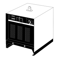
Details machine capabilities, dimensions, and output ratings.
Specific safety steps required before and during installation.
Guidelines for placing the welder for optimal airflow and operation.
Instructions on how to connect power supply to the machine.
Specifies required input circuit protection and wire gauges.
Detailed instructions for electrical hookup and grounding.
Procedures for safely connecting the gas supply cylinder.
Steps for changing the machine's input voltage configuration.
Instructions for attaching the work clamp and welding gun.
Guidance on setting the correct welding output polarity.
Steps for setting up welding gun consumables for proper wire feed.
Procedure for connecting the welding gun and cable assembly.
Essential safety rules for operating the welding machine.
Overview of the SP-250's intelligent welding system features.
Explanation of the keypad, display, and control modes.
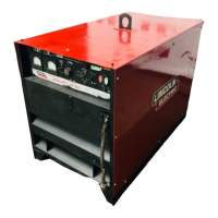
Key design elements and benefits contributing to machine performance.
Details on duty cycle ratings and performance specifications.
Constraints on machine operation, such as generator compatibility.
Detailed description of all front panel controls and their functions.
How to use arrow keys for parameter adjustments in different modes.
Step-by-step guide for performing welding operations.
Procedure for setting up a weld using the automatic mode.
Specific steps for performing spot welds using the auto mode.
Specific steps for performing stitch welds using the auto mode.
Information on selecting and installing appropriate wire drive rolls.
Instructions for loading wire spools onto the machine's spindle.
How to adjust the idle roll pressure for optimal wire feeding.
Overview of optional equipment and accessories available.
Details on ordering spare welding gun and cable assemblies.
Instructions for installing the optional spool gun adapter kit.
Steps for installing the spool gun module board inside the machine.
Procedure for installing the connection box for spool gun systems.
How to physically connect the spool gun to the machine.
Specific installation steps for older K531 spool gun kits.
Safety guidelines to follow before performing maintenance.
Recommended daily, periodic, and regular maintenance tasks.
Instructions for cleaning and inspecting wire feed drive components.
Procedure for cleaning the welding cable liner.
Maintenance for welding gun consumables like tips and nozzles.
Explanation of how the main power supply functions.
Details on power input and the function of the main transformer.
How current and voltage are rectified and controlled.
Explanation of how stable DC voltage output is maintained.
How the wire drive motor speed is controlled and monitored.
Explanation of the machine's overheat protection systems.
How Silicon Controlled Rectifiers are used to control output current.
Instructions on how to navigate and utilize the troubleshooting guide.
Steps for diagnosing and replacing PC boards, including static precautions.
Troubleshooting steps for issues related to welding output.
Troubleshooting steps for control panel, display, and alarm issues.
Troubleshooting steps for issues related to wire feed speed and delivery.
Troubleshooting steps for arc instability and weld quality.
Interpretation of on-screen messages and error codes.
Procedure to test the main transformer's primary and secondary voltages.
Test to quickly determine if an SCR is shorted or leaky.
Test to determine if SCRs can be gated ON and conduct current.
Procedure to test the resistance of each keypad button.
Tests to verify the wire drive motor and voltage feedback circuit.
Steps for safely removing and installing the main control PC board.
Steps for safely removing and installing the front panel keypad.
Procedure for removing and replacing the wire drive assembly.
Procedure for removing the SCR rectifier assembly.
Steps for safely removing and replacing the capacitor bank.
Procedure for safely removing and replacing the main transformer.
Steps for removing and replacing the cooling fan motor and blade.
Specifications for verifying repairs and confirming proper operation.
Diagram showing the layout of components on the G1992 PC board.
Diagram showing the layout of components on the G2252 PC board.
Schematic showing wiring connections for model code 9402.
Schematic showing wiring connections for model codes 9546 & 10002.
Schematic showing wiring connections for model codes 9723 & 10001.
Detailed schematic of the G1992 control PC board circuitry.
Detailed schematic of the G2252 control PC board circuitry.
| Brand | Lincoln Electric |
|---|---|
| Model | IDEALARC SP-250 |
| Category | Welding System |
| Language | English |