EasyManua.ls Logo

Lincoln Electric K1419-4 User Manual

Lincoln Electric K1419-4
112 pages
To Next Page IconTo Next Page
Page #1 background imageLoading...
Page #1 background image
®
RANGER 10,000 /10,000 PLUS
SVM168-B
April, 2010
Safety Depends on You
Lincoln arc welding and cutting
equipment is designed and built
with safety in mind. However,
your overall safety can be
increased by proper installation
. . . and thoughtful operation on
your part. DO NOT INSTALL,
OPERATE OR REPAIR THIS
EQUIPMENT WITHOUT READ-
ING THIS MANUAL AND THE
SAFETY PRECAUTIONS CON-
TAINED THROUGHOUT. And,
most importantly, think before
you act and be careful.
SERVICE MANUAL
For use with machine code numbers: Kohler 11041, 11151, 11394
Honda 11095, 11398
Robin/Subaru 11253. 11395
Sales and Service through Subsidiaries and Distributors Worldwide
Cleveland, Ohio 44117-1199 U.S.A. TEL: 216.481.8100 FAX: 216.486.1751 WEB SITE: www.lincolnelectric.com
World's Leader in Welding and Cutting Products
Copyright © Lincoln Global Inc.
Return to Master TOC Return to Master TOC Return to Master TOC Return to Master TOC
View Safety Info View Safety Info View Safety Info View Safety Info
All manuals and user guides at all-guides.com
all-guides.com

Table of Contents

Question and Answer IconNeed help?

Do you have a question about the Lincoln Electric K1419-4 and is the answer not in the manual?

Lincoln Electric K1419-4 Specifications

General IconGeneral
BrandLincoln Electric
ModelK1419-4
CategoryWelding System
LanguageEnglish

Summary

SAFETY

ELECTRIC SHOCK can kill.

Precautions to prevent electrocution from welding equipment.

WELDING and CUTTING SPARKS can cause fire or explosion.

Fire and explosion prevention measures during welding and cutting.

FOR ENGINE powered equipment.

Safety precautions for equipment powered by an engine.

ARC RAYS can burn.

Safety measures to protect eyes and skin from arc rays.

CYLINDER may explode if damaged.

Safety precautions for handling compressed gas cylinders.

FUMES AND GASES can be dangerous.

Hazards associated with welding fumes and gases and ventilation requirements.

INSTALLATION

TECHNICAL SPECIFICATIONS - RANGER® 10,000

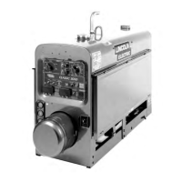
Detailed technical specifications for the RANGER® 10,000 welder.

TECHNICAL SPECIFICATIONS - RANGER 10,000 PLUS

Detailed technical specifications for the RANGER® 10,000 PLUS welder.

SAFETY PRECAUTIONS

General safety measures to be observed during installation.

AUXILIARY POWER

Information on the auxiliary power output capabilities of the welder.

AUXILIARY POWER WHILE WELDING

Permissible current limits for simultaneous welding and auxiliary power loads.

MACHINE GROUNDING

Proper procedures for grounding the welder for electrical safety.

ADDITIONAL SAFETY PRECAUTIONS

Extra safety measures to ensure safe operation.

WELDER OPERATION

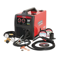
Basic steps and information for operating the welder.

WELDER OUTPUT

Specifications and information regarding the welder's output capabilities.

OPERATION

STARTING/SHUTDOWN INSTRUCTIONS

Procedures for starting and stopping the engine safely.

WELDING PROCESS

General guidelines for different welding processes.

STICK (CONSTANT CURRENT) WELDING

Procedures and settings for stick welding.

Welder Controls - Function and Operation

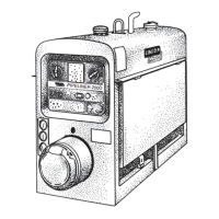
Explanation of the welder's controls and their functions.

TIG (CONSTANT CURRENT) WELDING

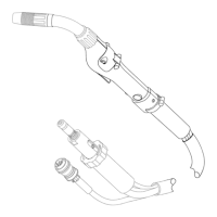
Procedures and settings for TIG welding with the optional module.

WIRE FEED WELDING PROCESSES (CONSTANT VOLTAGE)

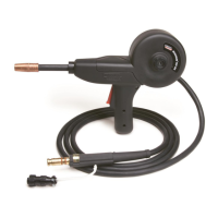
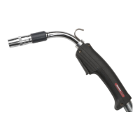
Procedures and settings for wire feed welding.

MAINTENANCE

Safety Precautions

Critical safety measures before performing any maintenance tasks.

ENGINE OIL CHANGE

Step-by-step instructions for changing the engine oil.

THEORY OF OPERATION

Battery, Starter, Engine, Excitation, Rotor, Stator, and Idler Solenoid

Explanation of the main electrical and mechanical components and their interaction.

ROTOR FIELD FEEDBACK AND AUXILIARY POWER

How rotor field feedback influences auxiliary power output.

WELD WINDING, REACTOR, AND RANGE SWITCH

How the weld winding, reactor, and range switch control welding current.

OUTPUT BRIDGE, CHOKE, POLARITY SWITCH, AND OUTPUT TERMINALS

Function of the output bridge, choke, and polarity switch in delivering power.

TROUBLESHOOTING & REPAIR

HOW TO USE TROUBLESHOOTING GUIDE

Instructions on how to effectively use the troubleshooting guide.

OUTPUT PROBLEMS

Troubleshooting for constant voltage (CV) welding output issues.

ENGINE PROBLEMS

Troubleshooting for engine starting, shutdown, and power output problems.

WELDING PROBLEMS

Troubleshooting steps for a cold welding arc.

ENGINE/ROTOR REMOVAL AND REPLACEMENT

Procedures for removing and replacing the engine and rotor.

ELECTRICAL DIAGRAMS

Related product manuals