J
Jennifer BellNov 6, 2025
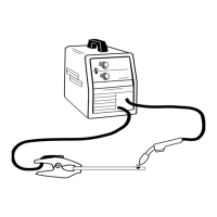
What to do if Lincoln Electric liquidarc Maxmig 330R Welding System wire is not feeding?
- SStephanie RobinsonNov 6, 2025
To troubleshoot rough wire feeding or when the wire isn't feeding but the drive rolls are turning on your Lincoln Electric Welding System, ensure the electrode lead and gun cable are tight, including the gun cable in the wire feeder contact block, the gun nozzle, and the gun tip. Also, verify that all work lead connections are secure. Inspect the gun cable, replacing it if necessary. Remove any obstructions in the gun and cable, replacing the gun and cable if needed. Refer to the Wire Drive Roll Section for proper drive roll installation. Remove, clean, install, and tighten components. Clean the cable or replace the liner. Replace any worn parts. Replace the contact tip and remove spatter. Set the idle roll pressure. Check the connection at the output studs for correct polarity. Clean the ...