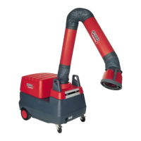
What to do if there are fumes when using a Lincoln Electric Mobiflex 200-M?
- DDeanna SanchezJul 28, 2025
If fumes are present while using a Lincoln Electric Welding System, use ventilation or exhaust to remove the fumes from your breathing zone.
What to do if there are fumes when using a Lincoln Electric Mobiflex 200-M?
If fumes are present while using a Lincoln Electric Welding System, use ventilation or exhaust to remove the fumes from your breathing zone.
Brand | Lincoln Electric |
---|---|
Model | Mobiflex 200-M |
Category | Welding System |
Language | English |
Core safety message emphasizing user responsibility and proper equipment handling.
Guidance that this manual should be used when assembling a new package.
Precautions to avoid electric shock during arc welding, including insulation and proper grounding.
Safety measures for working at heights or in elevated positions.
Using protective gear and screening to shield from arc radiation and sparks.
Wearing protective clothing to guard against molten slag and hot particles.
Mandatory use of safety glasses in the welding area and with side shields for chip welding.
Keeping flammable materials away or covered to prevent fire from sparks.
Placing the grounding clamp in an isolated spot when not welding to prevent short circuits.
Ensuring sufficient ventilation in the welding area, especially for toxic fumes.
Do not weld in the presence of chlorinated hydrocarbon vapors due to toxic gas formation.
Reference to CSA Standard W117.2-1974 for additional safety information.
Grounding the equipment chassis according to electrical codes and manufacturer recommendations.
Ensuring installation and maintenance are performed by a qualified electrician.
Disconnecting the machine from the power source before performing internal work.
Ensuring all covers and safety devices are kept in their proper locations.
Recording model name, serial number, and date of purchase for future reference.
Thoroughly read the operator's manual before using the equipment for safety.
Explanation of the information provided on the equipment's identification plate.
Explanation of WARNING and CAUTION symbols and their meaning for safety.
Sales specification, input voltage, power rating, sound level, and weight of the Mobiflex 200-M.
Physical dimensions including width, length, and height of the Mobiflex 200-M unit.
Minimum and maximum temperature, and maximum relative humidity for operation.
Extraction type, airflow rate, filter type, surface area, and efficiency of the system.
Details the specific Mobiflex models and accessories covered in this installation manual.
Lists the standard components included with the K1653-1 and K1653-2 Mobiflex 200-M base units.
Lists the components that make up the LFA 3.1 and 4.1 extraction arm.
Steps for assembling the rotating hinge, red plastic ring, and clamping pin for the extraction arm.
Instructions for placing rubber seals and connecting the flexible hose to the arm.
Details on adjusting friction connections at the base and middle hinges for arm movement.
Explains the function of lamp kits and automatic start/stop arc sensors.
Steps to prepare the hood for installing lamp kits and arc sensors, including removing parts.
Procedure for feeding the lamp and sensor leads through the hood and securing the lamp housing.
Instructions for installing the arc sensor into the lamp housing assembly.
Feeding the connecting cable through the hood and making connections at the control board.
Requirements for connecting the Mobiflex 200-M to a suitable power supply.
Instructions for routing the 13 ft. connecting cable through the arm's cable holders.
Sealing all hose joint connections with the provided rubber seals.
Steps for mounting the Transformer Relay Kit components in the control panel.
Instructions for making connections at the control panel for K1653-2 with transformer options.
Procedure for removing the terminal block jumper and connecting cable leads.
Key safety precautions to follow during the operation of the Mobiflex 200-M.
Ensuring filter, arm, and covers are installed for maximum protection during operation.
Steps for connecting power, positioning the hood, and general usage guidelines.
How to read and understand the filter maintenance indicator for timely filter replacement.
Cleaning the machine interior, filter compartment, and spark arrester every three months.
Annual checks of blower fan and housing by a qualified technician.
When to replace the filter based on damage, indicator, or reduced airflow.
Precautions for safe disposal of collected particulate matter and checking local regulations.
Step-by-step guide for disconnecting power and replacing the filter cartridge.
Diagnosing and resolving issues when the motor fails to start.
Troubleshooting motor humming without producing suction.
Resolving issues related to the motor stopping automatically due to overload.
Identifying causes and solutions for reduced suction.
Troubleshooting smoke or dust emission from the outlet grid.
Diagnosing and resolving excessive machine vibrations.
Guidance on contacting Lincoln Authorized Field Service for assistance with troubleshooting.
Diagram of the starter/overload circuit and its connections.
Diagram of the fan motor circuit, including capacitor and connections.
Diagram showing input power connection and related notes.
Diagram of the control panel, showing contactor, transformer, fuse, and terminal block.
Wiring diagram for the starter/overload in the K1653-2 control panel.
Wiring diagram for the fan motor in the K1653-2 unit.
Diagram showing input power connection for the K1653-2 unit.
Diagram showing the wiring for the work lamp and remote switch.
Diagram showing the wiring for the auto start/stop arc sensor.
Diagram illustrating control panel connections for integrated lamp and arc sensor options.
Diagram showing input power connection for the system with lamp and arc sensor.