Do you have a question about the Lincoln Electric Vantage 549 and is the answer not in the manual?
Warnings regarding diesel exhaust and product fumes concerning cancer and reproductive harm.
Crucial safety precautions for operating engine-powered equipment.
Safety measures against electric shock, arc rays, and burns.
Precautions for welding fumes, gases, sparks, and cylinder safety.
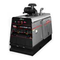
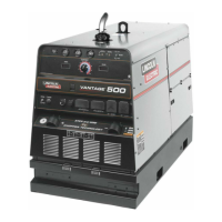
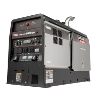
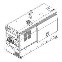
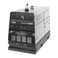
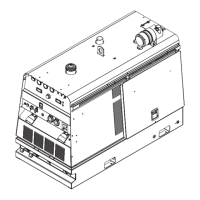
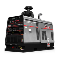
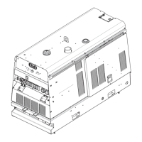
Overview of the VANTAGE® 549 and its technical characteristics.
Critical safety measures for installation and operation.
Proper location, ventilation, storing, lifting, towing, and vehicle mounting guidelines.
Instructions for battery, air cleaner, grounding, and welding cable connections.
Information on auxiliary power outlets and wire feeder connections.
Essential safety guidelines and recommended applications for the VANTAGE® 549.
Details on front panel controls, engine controls, gauges, meters, and indicators.
Covers common welding procedures, pulse welding, and various operation modes.
Information on using auxiliary power and typical fuel consumption data.
Critical safety guidelines to follow before performing maintenance.
Daily and weekly maintenance tasks for the equipment.
Covers engine oil, air cleaner, fuel filter, battery, and cooling system.
Step-by-step guide for testing and resetting Ground Fault Circuit Interrupters (GFCIs).
Instructions on how to effectively use the troubleshooting section to diagnose problems.
Identifies common engine issues, their causes, and recommended solutions.
Addresses issues related to battery charging, idle speed, and high idle engagement.
Troubleshooting problems with welding output, control, and auxiliary power.
Provides a comprehensive electrical wiring diagram for the VANTAGE® 549.
Diagram showing connections between VANTAGE, K867/K775, and LN-7 wire feeder.
Diagram for connecting engine welders to K867 via control cable adapter.
Diagram for connecting VANTAGE, K867, and LN-8 wire feeder.
Diagram for connecting engine welders with LN-25 and K624-1 remote control.
Diagram for connecting engine welders with K930 TIG Module.
Diagram for connecting engine welders with LN-742 wire feeder.
Diagram for connecting Tier 4 Final Welders (LN-25 Pro/LN-25/LN-15) with remote control.
Diagram for connecting Tier 4 Final Welders (LN-25) with K444-1 remote control.
Diagram for connecting Tier 4 Final Welders (LN-7) with remote control.
Diagram for connecting Tier 4 Final Welders with spool guns (K691-10/K488/K487).
Diagram for connecting Tier 4 Final Welders with Power Feed® 25M wire feeder.
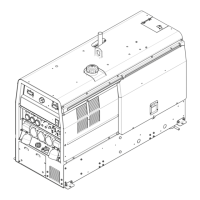
Detailed physical dimensions, weight, and trailer mounting hole locations.
Outlines Lincoln Electric's approach to customer advice and product use responsibility.
| Type | Engine Driven Welder |
|---|---|
| Fuel Type | Diesel |
| Welding Processes | Stick, TIG, MIG, Flux-Cored, Gouging |
| Max Output | 550A |
| Rated Output | 500A/40V/100% Duty Cycle |
| Auxiliary Power | 120/240 VAC |
| Engine | Kubota Diesel |
| Duty Cycle | 100% |