Do you have a question about the Lincoln Electric VANTAGE SVM178-B and is the answer not in the manual?
Safety precautions for operating engine-powered equipment, including shutdown before maintenance.
Warnings about cancer and reproductive harm from engine exhaust constituents.
Information on potential health effects of EMF fields from welding, especially for pacemaker wearers.
Precautions against electric shock, including insulation and dry gloves.
Warnings about avoiding breathing fumes and ensuring adequate ventilation.
Precautions to remove or cover fire hazards and avoid welding on containers.
Safety guidelines for handling compressed gas cylinders, including storage and securing.
Safety instructions for electrical connections, grounding, and power sources.
Details on engine, rated output, physical dimensions, and auxiliary power.
General safety instructions for installation and operation of the equipment.
Guidelines for proper welder placement to ensure airflow and exhaust ventilation.
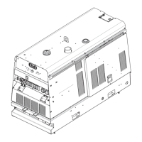
Instructions on how to safely lift the machine using the designated lift bale.
Essential checks and services before starting the engine, including oil and fuel.
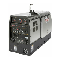
General instructions for operating the Vantage 500 welder.
Critical safety warnings and precautions to be followed during operation.
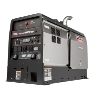
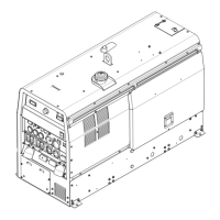
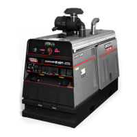
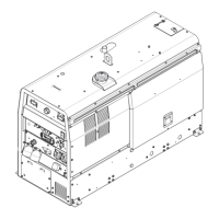
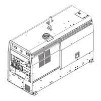
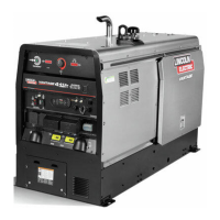
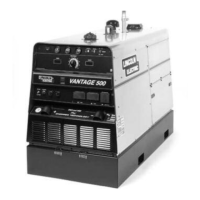
Overview of the Vantage 500's design, features, and engine.
Explanation of the various welder and engine controls on the front panel.
Procedures for starting, stopping, and operating the engine, including warm-up.
Details on operating the welder in different modes like Stick, TIG, and Wire Feed.
Description of accessories that can be installed by the user in the field.
Various torches, kits, and modules for TIG welding applications.
Details on compatible wire feeders and their features.
Essential safety measures to be taken before and during maintenance.
Daily and weekly maintenance tasks for the engine and machine.
Procedures for maintaining the engine, including oil and filter changes.
Instructions for cleaning, checking, and charging the battery.
Maintenance tasks for the welder and generator components like bearings and receptacles.
An overview of the Vantage 500's diesel engine, generator, and AC output.
Explanation of the engine's protection systems and the role of key components.
Description of how weld windings, rectifier, and power modules work together.
Details on the function and operation of the Weld Control PC Board.
Explanation of how IGBTs function as transistors in switching applications.
Explanation of how pulse width modulation affects machine output.
Overview of the high-speed control technology used in the welding machine.
Instructions on how to use the guide to locate and repair machine malfunctions.
Steps for diagnosing and replacing potentially faulty PC boards, including static precautions.
Troubleshooting steps for issues related to welding or auxiliary power output.
Common engine-related issues and their troubleshooting steps.
Procedures for removing and replacing the stator and rotor components.
Electrical wiring schematic for the Deutz engine model.
Electrical wiring schematic for the Cummins engine model.
Overall schematic of the machine for the Cummins engine.
Detailed schematic of the Weld Control PC Board.
Schematic diagram for the Chopper PC Board.
| Brand | Lincoln Electric |
|---|---|
| Model | VANTAGE SVM178-B |
| Category | Welding System |
| Language | English |